Determining method of arch dam abutment sliding block body bottom sliding face water seepage pressure

A technique for sliding blocks and determining methods, which is applied in special data processing applications, instruments, and electrical digital data processing, etc., and can solve problems such as calculation errors, inaccurate calculation results, and inability to obtain the length of the bottom sliding surface intuitively. The results are accurate

Active Publication Date: 2016-04-20
POWERCHINA XIBEI ENG
View PDF4 Cites 0 Cited by
  • Summary
  • Abstract
  • Description
  • Claims
  • Application Information

AI Technical Summary

Problems solved by technology

[0003] Since the bottom sliding surface is often a spatial surface, the length of the bottom sliding surface cannot be obtained intuitively. At the same time, for the part of the bottom sliding surface that does not directly intersect with the upstream pulling surface, this method often has a certain calculation error, making Calculations are not accurate enough

Method used


Image

  • Determining method of arch dam abutment sliding block body bottom sliding face water seepage pressure
  • Determining method of arch dam abutment sliding block body bottom sliding face water seepage pressure
  • Determining method of arch dam abutment sliding block body bottom sliding face water seepage pressure

Examples


Embodiment 1

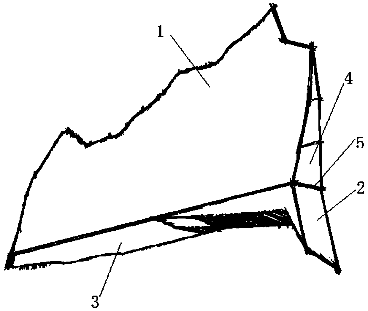
[0028] This embodiment provides a method for determining the water seepage pressure on the bottom sliding surface of the abutment sliding block of an arch dam, combining Figure 1-Figure 5 shown, including the following steps:

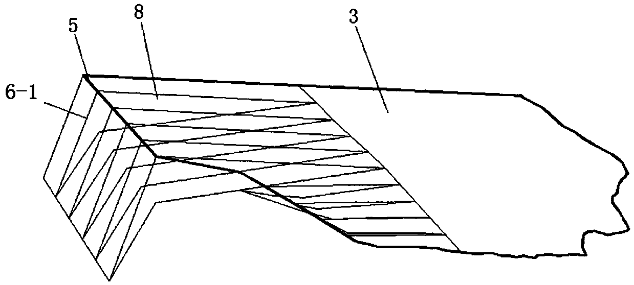
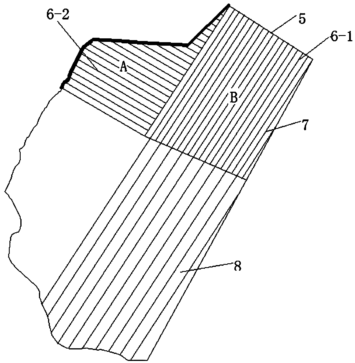
[0029] Step 1): According to a certain step value, a straight line perpendicular to the direction of the intersection line 5 between the upstream pulling surface and the bottom sliding surface is used as the bottom sliding surface splitting line 7 to split the bottom sliding surface 3 that directly intersects the upstream pulling surface. For the part, the part on the bottom sliding surface 3 that directly intersects with the upstream drawing surface is divided to form a layered structure;

[0030] Step 2): According to the layering results of step 1), each layer will form a subdivision unit 8, obtain the hydrostatic pressure at the upstream end of the bottom sliding surface of the subdivision unit 8, and obtain the curtain line position according to t...

Embodiment 2

[0038] On the basis of Embodiment 1, this embodiment will be further described in detail. The method for determining the water seepage pressure on the bottom sliding surface of the arch dam abutment sliding block in this embodiment will be described with a specific three-dimensional block 1, specifically including The following steps:

[0039] Step 1): If figure 2 and image 3 As shown, according to the 1m step value, a straight line 7 perpendicular to the direction of the intersection line 5 between the upstream pulling surface and the bottom sliding surface is used to divide the part of the bottom sliding surface 3 that directly intersects with the upstream pulling surface, and the bottom sliding surface 3 The part that directly intersects with the upstream drawing surface is subdivided to form a layered structure. The specific step value and subdivision direction in this step can be divided by yourself, and the actual needs of the site shall prevail.

[0040] Step 2): Ac...


PUM


Abstract

The invention belongs to the technical field of dam abutment slopes and mainly relates to a determining method of arch dam abutment sliding block body bottom sliding face water seepage pressure. A similar mathematical integral mode is adopted, finally, summation is performed after subdivision calculation is performed on a bottom sliding face, the problems that according to a traditional method, errors are large when the shape of the bottom sliding face is irregular, and usually, the calculation result is not ideal enough are avoided, and the calculation result of the bottom sliding face water seepage pressure is more accurate; the portion, not directly intersecting with the upstream pull-open face, of the upper edge of the bottom sliding face and the portion, directly intersecting with the upstream pull-open face, of the upper edge of the bottom sliding face are calculated separately, finally, summation is performed, and the calculation result is more accurate. Besides, due to the method, display can be completely achieved through a computer, and all data is converted into area and volume with shape and size and is more visual.

Description

technical field [0001] The invention belongs to the technical field of dam abutment slopes, and mainly relates to a method for determining the water seepage pressure of the bottom sliding surface of an arch dam abutment sliding block. Background technique [0002] The seepage pressure is a factor that cannot be ignored in the stability analysis and calculation of the abutment slope of an arch dam. When calculating the seepage pressure of the bottom sliding surface, the traditional method is to take three times the length of the arch end and compare it with the length of the corresponding bottom sliding surface. Small values ​​are calculated. [0003] Since the bottom sliding surface is often a spatial surface, the length of the bottom sliding surface cannot be obtained intuitively. At the same time, for the part of the bottom sliding surface that does not directly intersect with the upstream pulling surface, this method often has a certain calculation error, making The calc...

Claims


Application Information

Patent Timeline
Patent Type & Authority Applications(China)
IPC IPC(8): G06F17/50
CPCG06F30/367
Inventor 蔡云鹏李梦柏俊磊
Owner POWERCHINA XIBEI ENG
Why Eureka
Try Eureka