
Fire ventilation pipe valve

A technology for ventilation pipes and valves, which can be applied to lift valves, valve devices, engine components, etc., can solve problems such as increased manufacturing costs, increased valve weight, and limited effects.

Active Publication Date: 2017-11-28
GUANGXI NANNING DUNING VENTILATION PROTECTION EQUIP CO LTD
View PDF8 Cites 0 Cited by
  • Summary
  • Abstract
  • Description
  • Claims
  • Application Information

AI Technical Summary

Problems solved by technology

Since this kind of fire valve needs to ensure that it still has good sealing performance under high temperature conditions, it is necessary to minimize the deformation of the valve plate under high temperature conditions; for this reason, the current valve plate generally forms vertical reinforcement grooves on the surface. It can effectively suppress the bending deformation of the valve plate with respect to the horizontal plane; however, on the same plate, after the vertical reinforcement groove is formed, the horizontal reinforcement groove cannot be formed, which makes the valve plate easy to form bending deformation with respect to the vertical surface; when encountering high temperature When there is air flow and there is a certain air pressure in the pipeline, the heat is evenly distributed to the surface of the valve plate, causing the surface of the valve plate to deform uniformly in the transverse direction, which causes the valve plate to lean against the side of the sealing edge in the forward direction, and under the action of pressure, it will move backward deformation, resulting in obvious air leakage on this side; the current general solution is to greatly thicken the valve plate, which obviously greatly increases the manufacturing cost, especially the pressing of the vertical reinforcement groove, the processing difficulty is greatly increased, and Also make the weight of the whole valve significantly increase, the effect is also very limited

Method used


Image

  • Fire ventilation pipe valve
  • Fire ventilation pipe valve
  • Fire ventilation pipe valve

Examples


Embodiment Construction

[0013] Below in conjunction with accompanying drawing and embodiment the present invention is further described:

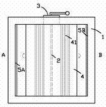
[0014] The basic part of the fire ventilation pipe valve is consistent with ordinary valves, such as figure 1 shown, including the short tube (extending inward from the paper, figure 1 blocked by the connecting flange), and the connecting flanges 1 at the front and rear ends of the short pipe; the short pipe is provided with a vertical rotating shaft 2, and the rotation of the rotating shaft 2 is controlled by the operating mechanism 3 outside the short pipe; the rotating shaft 2 is fixed with a vertical valve plate 4 that is symmetrical about the rotation axis; a vertical reinforcement groove 41 is formed on the valve plate 4; sealing edges matching the left and right sides of the valve plate 4 are also provided in the short pipe Bars 5A, 5B, the valve plate 4 is rotating with the rotating shaft 2; figure 1 In the paper, the outside of the paper is set as the f...


PUM


Abstract

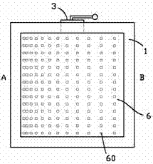
The invention provides a firefighting ventilating duct valve. The firefighting ventilating duct valve comprises a short pipe and connecting flanges at the two ends of the short pipe. The short pipe is internally provided with a vertical rotating shaft. Rotation of the rotating shaft is controlled by an operating mechanism outside the short pipe. Vertical valve plates symmetrical about the rotating shaft are fixed to the rotating shaft. A vertical direction strengthening groove is formed in each valve plate. Sealing edge strips matched with the left side and the right side of each valve plate are further arranged inside the short pipe. In the process that the valve plates rotate along with the rotating shaft to close the valve, one side of each valve plate backwards leans on one of the sealing edge strips, and the side is recorded as an A side corresponding to the valve; the other side of each valve plate forwards leans on the other sealing edge strip, and the side is recorded as a B side corresponding to the valve. A ventilating plate is further arranged at the front end of the short pipe and full of ventilating holes, and the distribution density of the ventilating holes has the following characteristic that the density of the ventilating holes is gradually decreased from the A side to the B side. The sealing performance of the firefighting valve can be significantly improved under the condition of high temperature when the valve is closed, and the cost is low.

Description

technical field [0001] The invention relates to the field of fire-fighting pipeline equipment, in particular to a fire-fighting ventilation pipeline valve. Background technique [0002] In the field of fire-fighting ventilation pipes, fire-fighting valves must be installed in the pipes. When a fire occurs in a building unit, if the fire spreads into the fire-fighting pipes, the fire-fighting valve must be closed to prevent the high-temperature air from being drawn out by the fan and affecting the external environment. The current fire-fighting valve mainly includes a short pipe, the two ends of the short pipe are provided with connecting flanges, and a valve plate that can rotate around a vertical axis is arranged in the short pipe, and the valve plate is operated by the operating mechanism outside the short pipe; when the valve When the plane of the plate is rotated to be perpendicular to the end face of the short pipe, the valve is fully open. When the valve plate is rotat...

Claims


Application Information

Patent Timeline
Patent Type & Authority Patents(China)
IPC IPC(8): F16K1/226
CPCF16K1/226
Inventor 顾锡红顾锡江梁玉星陆银波邓治宇
Owner GUANGXI NANNING DUNING VENTILATION PROTECTION EQUIP CO LTD
Learn More