Lighting device and display device

A technology for lighting devices and display panels, which is applied in the directions of lighting devices, lighting and heating equipment, light guides of lighting systems, etc., can solve the problems of uneven light emission, reduced display quality of liquid crystal display panels, uneven brightness of liquid crystal display panels, etc. Achieve uniform brightness and improve display quality

Inactive Publication Date: 2017-10-24
SAKAI DISPLAY PROD
View PDF6 Cites 0 Cited by
  • Summary
  • Abstract
  • Description
  • Claims
  • Application Information

AI Technical Summary

Problems solved by technology

Therefore, light tends to exit unevenly from the front surface of the light guide plate
Therefore, the illumination of the backlight unit becomes uneven, and in turn, the brightness of the liquid crystal display panel becomes uneven.
Therefore, the display quality of the liquid crystal display panel is degraded

Method used


Image

  • Lighting device and display device
  • Lighting device and display device
  • Lighting device and display device

Examples


Embodiment approach 1

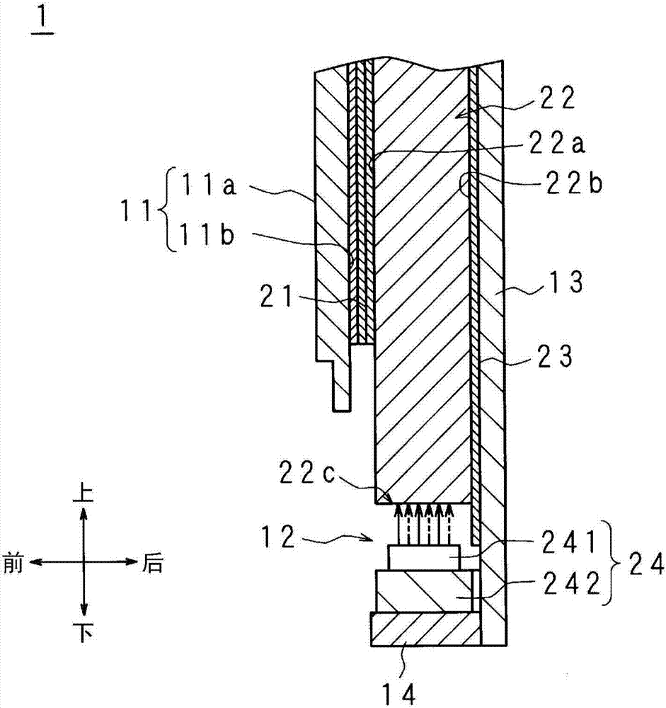
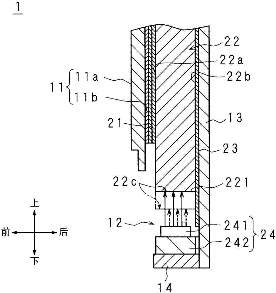
[0043] figure 1 as well as figure 2 It is a vertical cross-sectional view schematically showing the structure of the display device 1 according to Embodiment 1 of the present invention. exist figure 1 as well as figure 2 The vicinity of the lower side of the light guide plate 22 to be described later is shown in . and, in figure 1 The left or right end of the light guide plate 22 is shown in figure 2 The center part in the left-right direction of the light guide plate 22 is shown in .

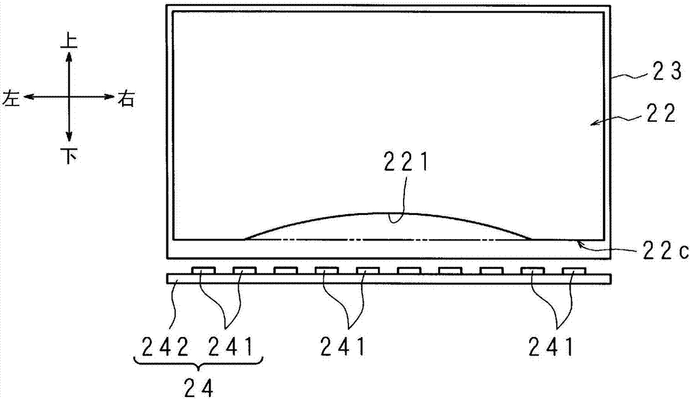
[0044] image 3 It is a front view schematically showing the positional relationship between the light guide plate 22 and the light source unit 24 included in the backlight unit 12 of the lighting device according to Embodiment 1 of the present invention.

[0045] The display device 1 of the present embodiment is configured as, for example, a television receiver, an electronic signboard, or a monitor for a personal computer.

[0046] First, the configuration of the display device 1 w...

Embodiment approach 2

[0101] Figure 5 It is a front view schematically showing the positional relationship between the light guide plate 22 and the light source unit 24 included in the backlight unit 12 according to Embodiment 2 of the present invention. Figure 5 with Embodiment 1 image 3 correspond. However, illustration of the reflection sheet 23 is omitted.

[0102] The backlight unit 12 of the present embodiment has substantially the same configuration as the backlight unit 12 of the first embodiment. Hereinafter, differences from Embodiment 1 will be described, and other portions corresponding to Embodiment 1 will be given the same reference numerals, and descriptions thereof will be omitted.

[0103] Generally, less important video is displayed on the left and right ends of the display area of ​​the display panel 11 than on the center in the left and right directions. Therefore, it may be more desirable for the user to uniformly brighten the display area in the range where an important...

Embodiment approach 3

[0109] Image 6 It is a front view schematically showing the positional relationship between the light guide plate 22 and the light source unit 24 included in the backlight unit 12 according to Embodiment 3 of the present invention. Image 6 with embodiment 2 Figure 5 correspond.

[0110] The backlight unit 12 of the present embodiment has substantially the same configuration as the backlight unit 12 of the second embodiment. Hereinafter, differences from Embodiment 2 will be described, and other portions corresponding to Embodiment 2 will be given the same reference numerals, and descriptions thereof will be omitted.

[0111] In Embodiment 2, the protrusions 222, 222 are disposed at a distance of W / 9 from the left and right ends of the light guide plate 22, but in this embodiment, the protrusions 222, 222 are disposed at a distance from the left and right ends of the light guide plate 22. The left and right end portions of the optical panel 22 are separated by a distance ...


PUM


Abstract

The present invention provides a lighting device and a display device capable of uniform lighting. The temperature of the light source part (24) due to heat generated during light emission is higher in the left-right direction central part than in the peripheral direction (left-right direction in the drawing) of the light guide plate (22) at both ends. Therefore, the central portion in the left-right direction of the peripheral edge portion of the light guide plate (22) tends to thermally expand. Therefore, as far as the light guide plate (22) is concerned, when the light guide plate (22) is not thermally expanded (that is, when the lighting device is not used), the part farthest from the light source part (24) time) the most significant approach to the light source part (24). Therefore, when the lighting device is used, the distance between the peripheral surface of the light guide plate (22) and the light source portion (24) is uniform. Therefore, the amount of incident light from the light source unit (24) to the inside of the light guide plate (22) is uniform in the left and right directions. Therefore, the illumination by the illumination device is uniform in the left and right directions.

Description

technical field [0001] The present invention relates to an illuminating device and a display device in which light emitted from a light source unit is emitted from one surface of a light guide plate. Background technique [0002] The liquid crystal display device has a liquid crystal display panel and a backlight unit that illuminates the liquid crystal display panel from the rear surface side of the liquid crystal display panel. [0003] Hereinafter, a case where a liquid crystal display panel is arranged in a vertical orientation will be described. [0004] Conventionally, an edge light type backlight unit has been proposed (see Patent Document 1). In the edge light type backlight unit, a rectangular light guide plate is arranged on the rear surface side of the liquid crystal display panel with an optical sheet group interposed therebetween, and a light source unit is arranged to face the lower end surface of the light guide plate. The light source unit is configured by ...

Claims


Application Information

Patent Timeline
Patent Type & Authority Patents(China)
IPC IPC(8): F21K9/20G02F1/13357F21Y115/10
CPCG02B6/002G02B6/0085G02B6/0073G02B6/0088G02B6/009
Inventor 山川亮
Owner SAKAI DISPLAY PROD
Why Eureka
Try Eureka