
Pneumatic tire

A technology of pneumatic tires and tires, which is applied in the field of tread patterns, can solve the problems that the shared force cannot contribute to it, large lateral grip, etc., and achieve the effect of improving turning performance and increasing lateral grip

Active Publication Date: 2016-05-18
SUMITOMO RUBBER IND LTD
View PDF5 Cites 4 Cited by
  • Summary
  • Abstract
  • Description
  • Claims
  • Application Information

AI Technical Summary

Problems solved by technology

Thus, while the shared force in the tire axial direction of the compacted snow in the shoulder circumferential main groove contributes to the shared force against the lateral force during cornering, the compaction in the axially outer crown lateral groove The shared force in the tire axial direction of the snow and the shared force in the tire axial direction of the compacted snow in the shoulder lateral groove cannot contribute to it
[0007] Therefore, it is difficult to generate a large lateral grip against compacted snow, and the tire cannot exhibit sufficient cornering performance on snowy roads

Method used


Image

  • Pneumatic tire
  • Pneumatic tire
  • Pneumatic tire

Examples


comparative test 1

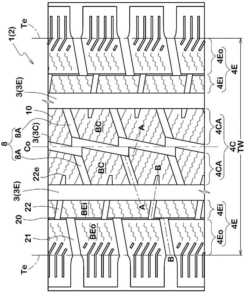
[0129] based on figure 1 The tread pattern shown in is experimentally manufactured for a studless anti-skid tire with a size of 205 / 65R16 (rim size 16×6.5J). The specifications of grooves, crown oblique grooves, central circumferential main grooves and sipe are changed to those listed in Table 1. Additionally, all tires have substantially the same specifications.

[0130] The tires were tested for snow performance and abrasion resistance as follows.

[0131] (Turning performance on snow)

[0132] The test tires are installed on all four wheels of a medium-sized truck (engine displacement 2800cc, front tire pressure 390kPa, rear tire pressure 350kPa, load 50% of the maximum load), and the test driver is on the snow-covered road at the tire test site Lateral grip during driving was evaluated. In Table 1, the results are represented by an index based on the comparative example tire ReF.1 (which is 100), wherein the larger the index, the greater the lateral grip, ie, the bette...

comparative test 2

[0136] based on figure 1 The tread pattern shown in , was experimentally manufactured for a studless tire with a size of 205 / 65R16 (rim size 16×6.5J), and the specifications of the central circumferential main groove, crown oblique groove and slit were changed for the specifications listed in Table 2. Additionally, all tires have substantially the same specifications.

[0137] The tires were tested for snow performance as above and wet performance as below. Table 2 shows the results of the snow performance test.

[0138] (wet performance)

[0139] Using the test vehicle described above, the test driver evaluated the steering stability during running on the wet road surface of the tire test field. In Table 2, the results are represented by indices based on Comparative Example tire ReF.A1 (which is 100), wherein the larger the index, the better the wet performance.

[0140] As shown in Tables 1 and 2, the cornering performance of the working example tires on snow was improv...


PUM


Abstract

The present invention provides a pneumatic tire. Each shoulder land region defined by a shoulder circumferential main groove is provided with a circumferential narrow groove and axially inner and outer shoulder oblique grooves and extending therefrom. The axially outer shoulder oblique grooves are inclined with respect to the tire axial direction to one direction. The axially inner shoulder oblique grooves are inclined with respect to the tire axial direction to one direction opposite to that of the axially outer shoulder oblique grooves. Crown oblique grooves are inclined with respect to the tire axial direction to one direction same as that of the axially outer shoulder oblique grooves. Imaginary extensions of the axially outer shoulder oblique grooves are not overlapped with openings of the axially inner shoulder oblique grooves at the circumferential narrow groove. Imaginary extensions of the axially inner shoulder oblique grooves are not overlapped with openings of the crown oblique grooves at the shoulder circumferential main groove, and are not overlapped with openings of the axially outer shoulder oblique grooves at the circumferential narrow groove. Imaginary extensions of the crown oblique grooves are not overlapped with openings of the axially inner shoulder oblique grooves at the shoulder circumferential main groove.

Description

technical field [0001] The present invention relates to pneumatic tires, and more particularly to a tread pattern capable of improving lateral grip performance on snowy roads. Background technique [0002] Japanese Patent Application Publication No. 2013-189128 discloses a pneumatic tire provided in a tread portion, the pneumatic tire having: two shoulder circumferential main grooves; a central circumferential main groove provided between the two shoulder circumferential main grooves a groove; an intermediate circumferential secondary groove disposed between the central circumferential main groove and each shoulder circumferential main groove; disposed in a portion between each of the central circumferential main groove and the intermediate circumferential secondary grooves, to Axial inner crown lateral grooves dividing the portion into axial inner crown blocks; provided in a portion between each of the shoulder circumferential main grooves and the adjacent intermediate circ...

Claims


Application Information

Patent Timeline
Patent Type & Authority Applications(China)
IPC IPC(8): B60C11/03B60C11/12
CPCB60C11/0306B60C11/1236B60C2011/0344B60C2011/0346B60C2011/0348B60C2011/0395B60C2011/1213B60C2011/1254B60C11/13B60C2011/0372B60C2011/0374
Inventor 黒泽大佐藤拓也
Owner SUMITOMO RUBBER IND LTD
Features
  • Generate Ideas
  • Intellectual Property
  • Life Sciences
  • Materials
  • Tech Scout
  • Unparalleled Data Quality
  • Higher Quality Content
  • 60% Fewer Hallucinations
Learn More