
Film sticking device

A technology of film sticking device and film sticking mechanism, which is applied in the directions of packaging, package protection, transportation and packaging, etc., can solve the problems of low efficiency, achieve fast film sticking, and improve the effect of film sticking efficiency

Active Publication Date: 2019-04-19
FU DING ELECTRONICSAL TECH JIASHAN +2
View PDF5 Cites 0 Cited by
  • Summary
  • Abstract
  • Description
  • Claims
  • Application Information

AI Technical Summary

Problems solved by technology

In traditional film sticking, workers usually peel off the release paper at one end of the film material by hand, and stick the film material on the surface of the workpiece, but the efficiency is low

Method used


Image

  • Film sticking device
  • Film sticking device
  • Film sticking device

Examples


Embodiment Construction

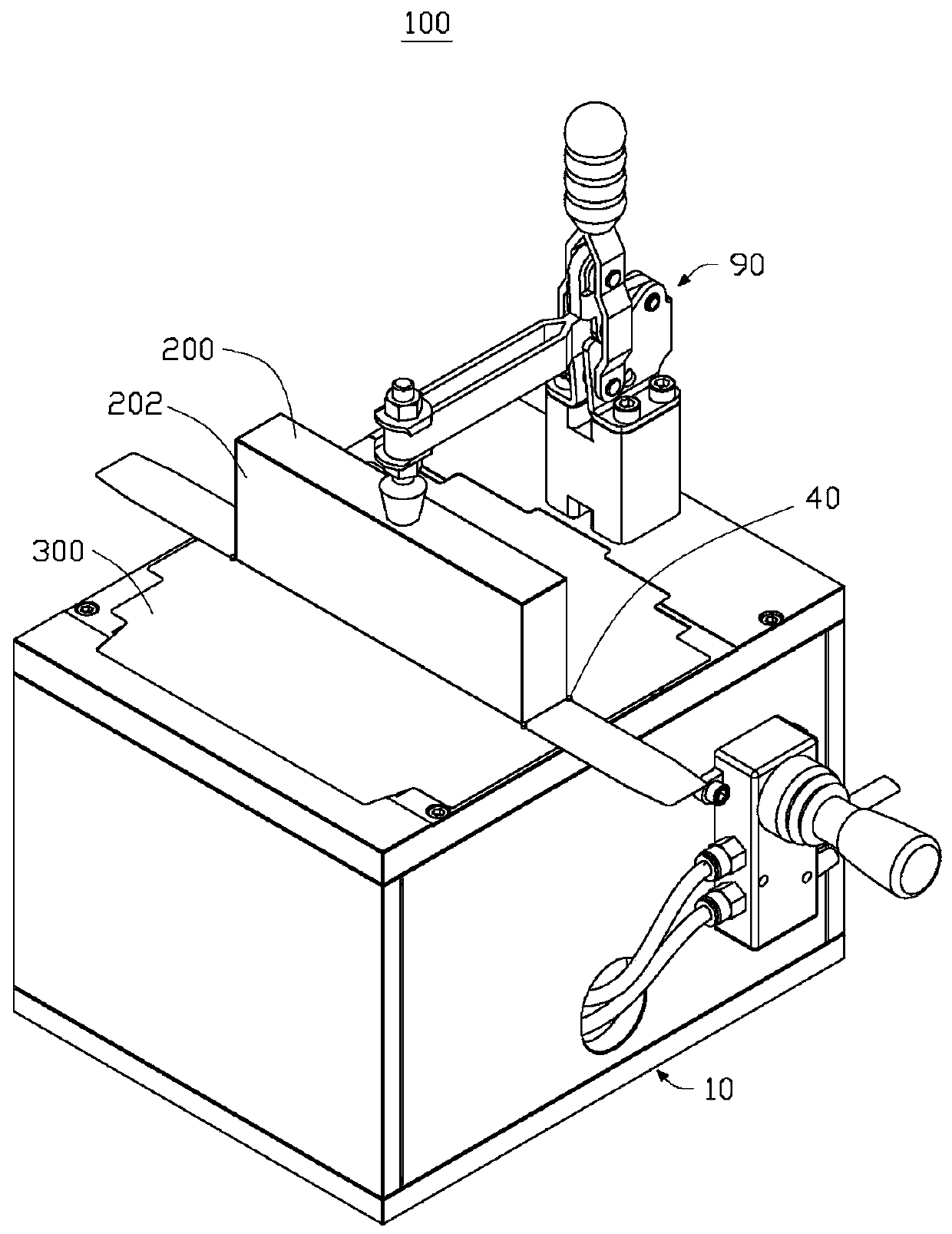
[0063] see figure 1 , this embodiment provides a film sticking device 100 for sticking a film material 300 on a workpiece 200 . In this embodiment, the workpiece 200 is in the shape of a regular hexahedron, and the workpiece 200 has two opposite sides 202 .

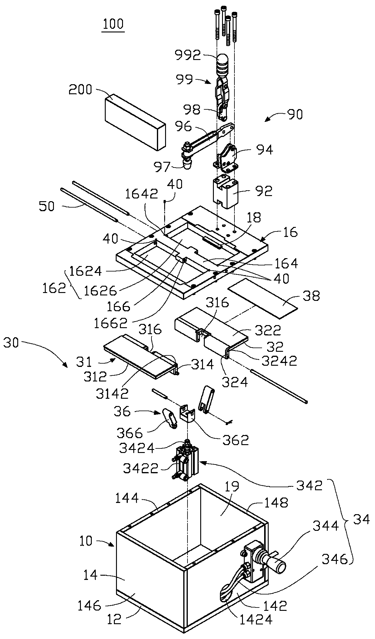
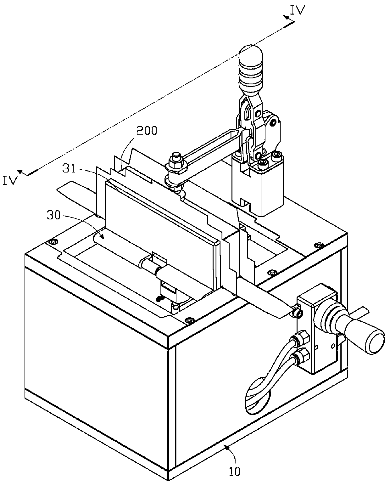
[0064] see figure 1 and figure 2 , the film sticking device 100 includes a base 10 and a film sticking mechanism 30 disposed on the base 10 .

[0065] see again figure 2 , the base 10 is in the shape of a rectangular parallelepiped box, which includes a bottom plate 12 , a plurality of side plates 14 and a top plate 16 arranged around the periphery of the bottom plate 12 . The bottom panel 12 , the side panels 14 and the top panel 16 together define a receiving space 19 . In this embodiment, the bottom plate 12 is substantially rectangular plate-shaped. The number of side plates 14 is four, which include a first side plate 142 and a second side plate 144 which are substantially parallel to each other, and a third ...


PUM


Abstract

A film sticking device comprises a pedestal and a film sticking mechanism arranged on the pedestal; the pedestal is provided with a support portion used for placing a workpiece; the film sticking mechanism comprises a drive unit arranged on the pedestal and a bearing unit driven by the drive unit to rotate, thus bearing film material; the bearing unit is connected with the pedestal in a rotary manner, and adjacent to the support portion; the drive unit can drive the bearing unit to rotate relative to the support portion, so the bearing unit can be pressed on the workpiece, and the film material on the bearing unit can be attached on the workpiece. The film sticking device can use the drive unit to drive the bearing unit so as to rotate relative to the workpiece, so the film material on the bearing unit can be attached on the surface of the workpiece, thus improving film sticking efficiency.

Description

technical field [0001] The invention relates to a film sticking device. Background technique [0002] Film materials are generally attached to the surface of electronic products to protect the appearance of electronic products and prevent the shell of electronic products from being bumped, scratched or dusty. Traditional film sticking usually requires workers to directly peel off the release paper at one end of the film material by hand, and stick the film material on the surface of the workpiece, but the efficiency is low. Contents of the invention [0003] In view of the above situation, the present invention provides a film sticking device capable of improving efficiency. [0004] A film sticking device, which includes a base and a film sticking mechanism arranged on the base. The supporting part of the film material, the supporting part is rotatably connected to the base and adjacent to the supporting part, the driving part can drive the supporting part to rotate rel...

Claims


Application Information

Patent Timeline
Patent Type & Authority Patents(China)
IPC IPC(8): B65B33/02B65B57/02
Inventor 李学文薛海河
Owner FU DING ELECTRONICSAL TECH JIASHAN
Learn More