Arrangement for connecting components

A technology for parts and heads, applied in the field of devices for connecting parts, can solve problems such as difficulty in establishing

Inactive Publication Date: 2016-05-18
约尔格·施瓦茨比奇
View PDF6 Cites 0 Cited by
  • Summary
  • Abstract
  • Description
  • Claims
  • Application Information

AI Technical Summary

Problems solved by technology

However, this shape of the helical spring is difficult to establish, especially when the helical spring is manufactured from hard spring steel for reasons of mechanical strength

Method used


Image

  • Arrangement for connecting components
  • Arrangement for connecting components
  • Arrangement for connecting components

Examples


Embodiment Construction

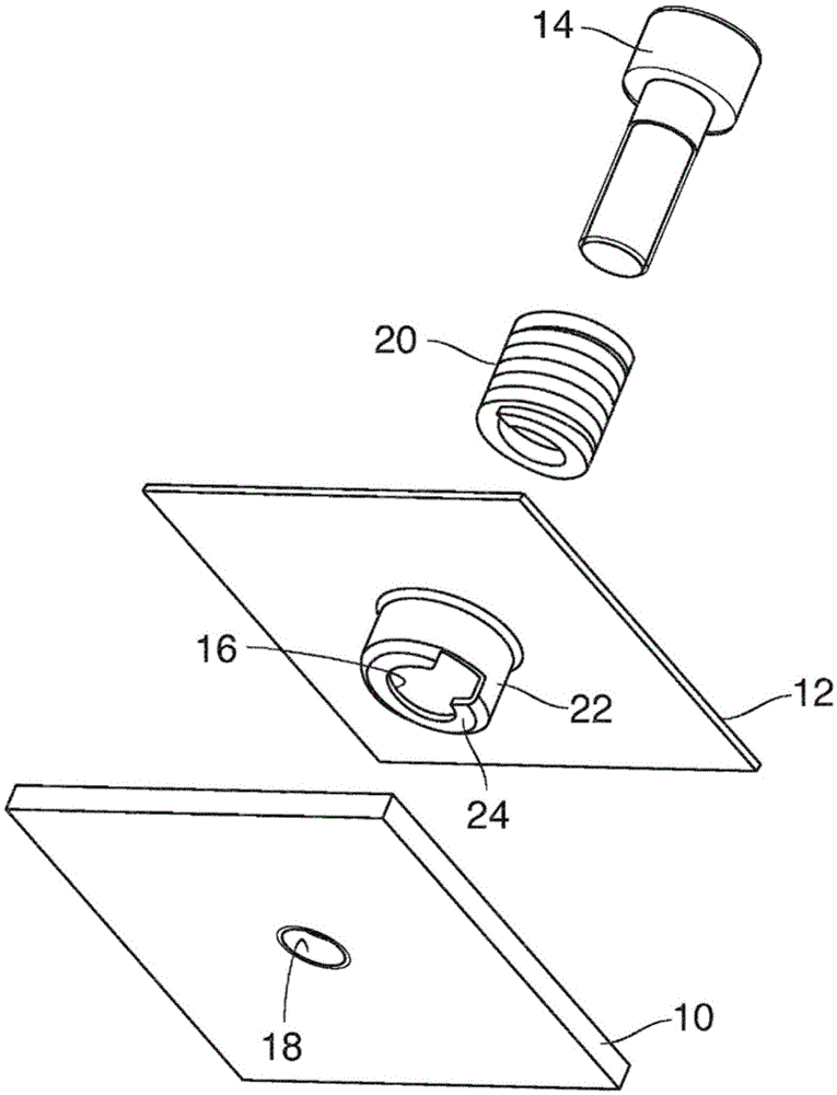
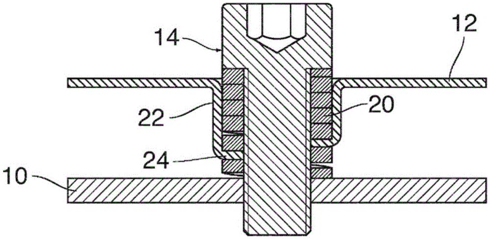
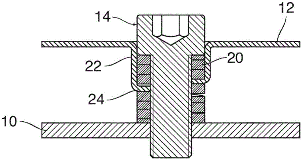
[0028] figure 1 A connecting device is shown for connecting the first part 10 to the plate-shaped second part 12 (for example, sheet metal) while being spaced apart. To this end, a screw 14 is provided, which is inserted through the screw hole 16 of the component 12 and screwed into the threaded hole 18 of the component 10. The coil spring 20 surrounding the threaded shaft of the screw 14 serves as a spacer between the parts 10 and 12. The coil spring 20 is formed by winding a spring wire having a rectangular cross section, for example.

[0029] The screw hole 16 of the second part 12 is formed at the bottom of the pot-shaped recess 22 which is embossed in the sheet metal of the part 12. At the periphery of the screw hole 16, the bottom of the recess 22 forms a threaded structure 24, which is shaped as a spiral flange, which is interrupted at one point and forms a single spiral loop. The recess 22, the screw hole 16, and the thread structure 24 can be stamped and embossed in th...


PUM


Abstract

The invention relates to an arrangement for connecting a first component (10) having a threaded bore (18) with a second component (12) by means of a screw (14) and a helical spring (20) surrounding it, which passes through the second component (12) and engages with a threaded structure (24) of this component, so that its section located between the two components forms a spacer with an adjustable axial dimension, characterized in that the second component (12) has a pot-shaped indentation (22) which receives a section of the helical spring (20) and the bottom of which forms the threaded structure (24).

Description

Technical field [0001] The present invention relates to a device for connecting a first part having a threaded hole with a second part through a screw and a coil spring surrounding the screw. The coil spring passes through the second part and engages with the thread structure of the part so that the screw The part of the spring located between these two parts forms a spacer with an adjustable axial dimension. Background technique [0002] With such a device, by clamping the two parts arranged in a mutually spaced manner with a spacer sandwiched between them, the two parts can be firmly connected. The spacer then allows to offset the tolerance in the space between these two parts. [0003] When there is proper frictional contact between the screw and the coil spring, the coil spring can be entrained to rotate when the screw is screwed in, so that the spring changes its axial position relative to the thread structure until the end of the spring The first component is joined and the...

Claims


Application Information

Patent Timeline
Patent Type & Authority Applications(China)
IPC IPC(8): F16B5/02F16B37/12
CPCF16B5/0233F16B5/0266F16B37/12
Inventor 约尔格·施瓦茨比奇
Owner 约尔格·施瓦茨比奇
Why Eureka
Try Eureka