AI technical title is built by Patsnap AI team. It summarizes the technical point description of the patent document.
A junction box and electric wire technology, applied in the field of junction boxes, can solve the problems of junction boxes not having enough use effects, etc.
Active Publication Date: 2016-06-01
安徽智达电气科技有限公司
View PDF6 Cites 0 Cited by
Summary
Abstract
Description
Claims
Application Information
AI Technical Summary
This helps you quickly interpret patents by identifying the three key elements:
Problems solved by technology
Method used
Benefits of technology
Problems solved by technology
[0003] In daily use, because the wires are too long, it is necessary to use the junction box to store some wires. The existing junction box does not have this function, and the use effect is not enough. Further improvement is needed
Method used
Image
Click on the blue label to locate the original text in one second.
Reading with bidirectional positioning of images and text.
Examples
Embodiment 1
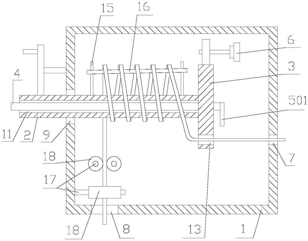
[0031] refer to figure 1 , 2 :
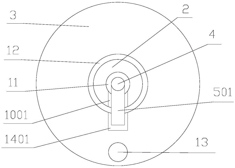
[0032] A junction box capable of storing wires proposed by the present invention includes a box body 1, a rotating shaft 2, a rotating wheel 3, a connecting rod 4, a connecting plate 501, a driving mechanism 6, and a plurality of limit units.
[0033] The box body 1 is provided with a wire inlet hole 7, a wire outlet hole 8, and a through hole 9. The wire inlet hole 7 and the through hole 9 are respectively placed on two opposite side walls of the box body 1. The axis of the wire inlet hole 7 is in line with the through hole. The axes of the holes 9 are parallel.
[0034] The rotating shaft 2 is placed in the through hole 9, and the rotating shaft 2 is rotatably connected with the through hole 9. The first end of the rotating shaft 2 is placed inside the box body 1 and is arranged close to the inlet hole 7. The first end surface of the rotating shaft 2 is provided with a receiving groove 1001 The second end of the rotating shaft 2 is placed ...
Embodiment 2
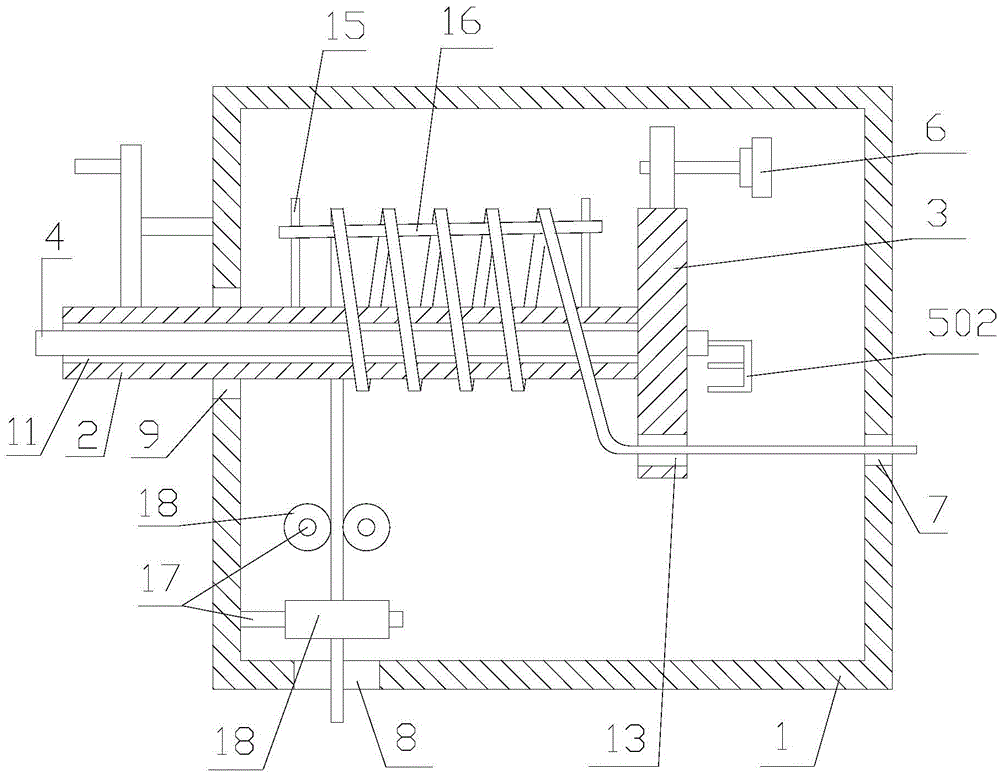
[0049] combine image 3 , 4 :
[0050] A junction box capable of storing electric wires proposed by the present invention includes a box body 1, a rotating shaft 2, a rotating wheel 3, a connecting rod 4, a connecting plate 502, a driving mechanism 6, and a plurality of position-limiting units.
[0051] The box body 1 is provided with a wire inlet hole 7, a wire outlet hole 8, and a through hole 9. The wire inlet hole 7 and the through hole 9 are respectively placed on two opposite side walls of the box body 1. The axis of the wire inlet hole 7 is in line with the through hole. The axes of the holes 9 are parallel.
[0052] The rotating shaft 2 is placed in the through hole 9, and the rotating shaft 2 is rotationally connected with the through hole 9. The first end of the rotating shaft 2 is placed inside the box body 1 and is arranged close to the wire inlet hole 7. The first end surface of the rotating shaft 2 is provided with a receiving groove 1002 The second end of the...
PUM
Abstract
The invention discloses a junction box capable of storing electric wires. The junction box comprises a box body, rotation shaft, a rotary wheel, a connecting rod, a connecting plate and a driving mechanism, wherein a wire-inlet hole, a wire-outlet hole and a through hole are formed in the box body; the wire-inlet hole and the through hole are formed in the two side walls of the box body; the rotation shaft is arranged in the through hole, and rotationally connected with the through hole; the first end of the rotation shaft is arranged on the inner side of the box body and close to the position of the wire-inlet hole; an accommodating groove is formed in the end plane of the first end of the rotation shaft; the second end of the rotation shaft is arranged on the outer side of the box body; the axial line of the rotation shaft is parallel or overlaid with the axial line of the wire-inlet hole; a connecting channel penetrating through the first end plane and the second end plane of the rotation shaft is formed in the rotation shaft; the length direction of the connecting channel is parallel to the axial line of the rotation shaft; a mounting hole is formed in the rotary wheel; the rotary wheel is rotationally mounted on the rotation shaft through the mounting hole; a wire-passing hole is formed in the rotary wheel; and an accommodating groove is formed in the end plane, corresponding to the first end of the rotation shaft, of the rotary wheel. The junction box is simple in structure and convenient to use.
Description
technical field [0001] The invention relates to the technical field of electrical equipment, in particular to a junction box capable of storing electric wires. Background technique [0002] The junction box is one of the electrical accessories. When used, the wires pass through the wire tube, and the junction box is used as a transition at the joint of the wire. The wire tube is connected to the junction box, and the wires in the wire tube are in the junction box. Connected together, it plays the role of protecting the wires and connecting the wires. [0003] In daily use, because the wires are too long, it is necessary to use the junction box to store some wires. The existing junction box does not have this function, and the use effect is not enough, which needs further improvement. Contents of the invention [0004] In order to solve the technical problems in the background technology, the present invention proposes a junction box capable of storing electric wires, whic...
Claims
Application Information
Patent Timeline
Application Date:The date an application was filed.
Publication Date:The date a patent or application was officially published.
First Publication Date:The earliest publication date of a patent with the same application number.
Issue Date:Publication date of the patent grant document.
PCT Entry Date:The Entry date of PCT National Phase.
Estimated Expiry Date:The statutory expiry date of a patent right according to the Patent Law, and it is the longest term of protection that the patent right can achieve without the termination of the patent right due to other reasons(Term extension factor has been taken into account ).
Invalid Date:Actual expiry date is based on effective date or publication date of legal transaction data of invalid patent.

