Wiring terminal connector for LED

A terminal and connector technology, which is applied in the direction of connection, conductive connection, clamping/spring connection, etc., can solve the problems of complicated wiring, large bending force, and inconvenient off-line, so as to simplify the steps of wiring and off-line, Good elasticity and effect of applying force and simplifying operability

Inactive Publication Date: 2016-06-08
JIANGMEN KREALUX ELECTRICAL APPLIANCES
View PDF8 Cites 0 Cited by
  • Summary
  • Abstract
  • Description
  • Claims
  • Application Information

AI Technical Summary

Problems solved by technology

In this way, the existing terminal blocks continue to show various changes in structure, and the structures of each terminal block are also different, and the complexity and connection methods are also different.
Although the structures of each terminal block are different, the biggest disadvantage of the existing terminal block is that it cannot be completed in one step when wiring, and often requires multiple steps of operation or wiring to complete the wiring work, and the wiring is complicated.
Especially for those shells that need to be opened, use connectors or fixings, such as bolts, rivets, etc. to connect the metal end of the wire to the metal conductor in the terminal, and then close the connector terminal to realize the wire connection. On the device, the wiring of this kind of structure is complicated, and the case needs to be opened again when it is off-line, and it is extremely inconvenient to go off-line
[0003] Although some people have invented a terminal that can be used for one-time wiring, due to the complex structure of this type of terminal, the wiring effect is not ideal, and the service life is not long, it cannot meet the current diversified wiring requirements.
[0004] Chinese Patent No. CN201110077533.6 "Operating Device for Electrolytic Wire Clamp" and German Patent No. DE102010014143 "Electronic Terminal Button Operating Equipment" both disclose the same type of terminal structure. One end of the designed pressing arm is connected to the back of the housing, and the other end is connected to the upper surface of the housing, and the first and second pressing arm parts of the pressing arm match the direction of the back of the housing and the direction of the upper surface of the housing respectively. The pressing arm of this structure It needs to straddle the back and upper part of the housing. At the same time, because the pressing arm has a certain curvature, which is similar to the "7" shape of the vertical angle. When pressing the pressing arm, the bending force on the first pressing arm part is relatively large, and the service life of the pressing arm is relatively large. After a long time, it is easy to lose elasticity, causing the entire terminal to be scrapped; in addition, the housing needs to be designed with a groove that matches the pressing arm. When the pressing arm occupies a large area on the back of the housing and the upper surface of the housing, the area of ​​the groove is also large. It is easy to cause foreign matter to enter the housing from the groove and contact the contact frame, and there is a risk of accidents
And the contact frame adopts two left and right plate springs to clamp the wires to realize wiring. The force of the button is applied to the sliding slope to open the gap between the two plate springs. Simultaneous application of force by the slope will increase the difficulty of opening the two leaf springs, and the force exerted by pressing the button is also large, which is not conducive to convenient wiring and humanized operation

Method used


Image

  • Wiring terminal connector for LED
  • Wiring terminal connector for LED
  • Wiring terminal connector for LED

Examples


Embodiment 1

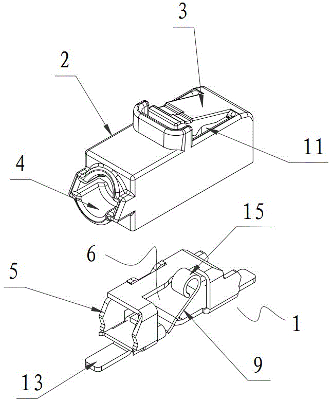
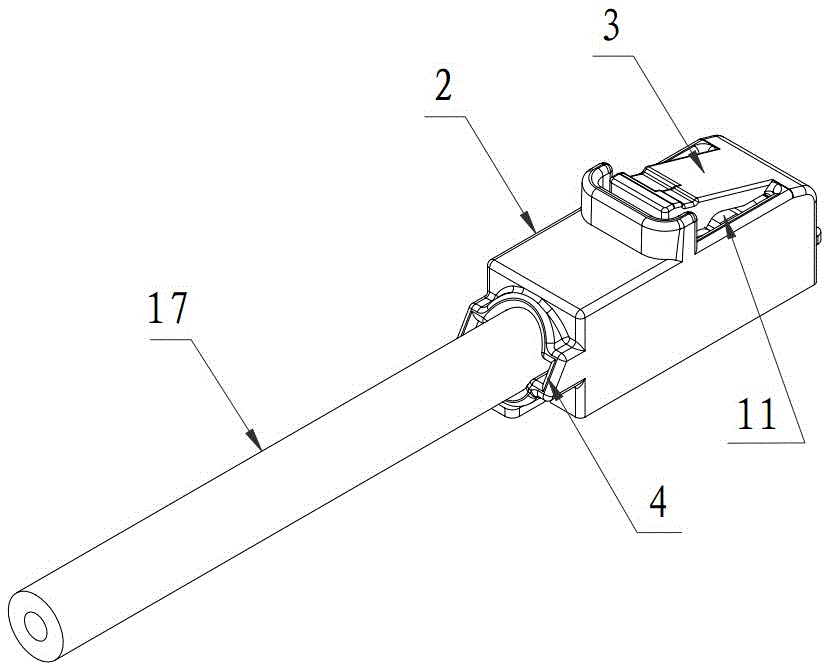
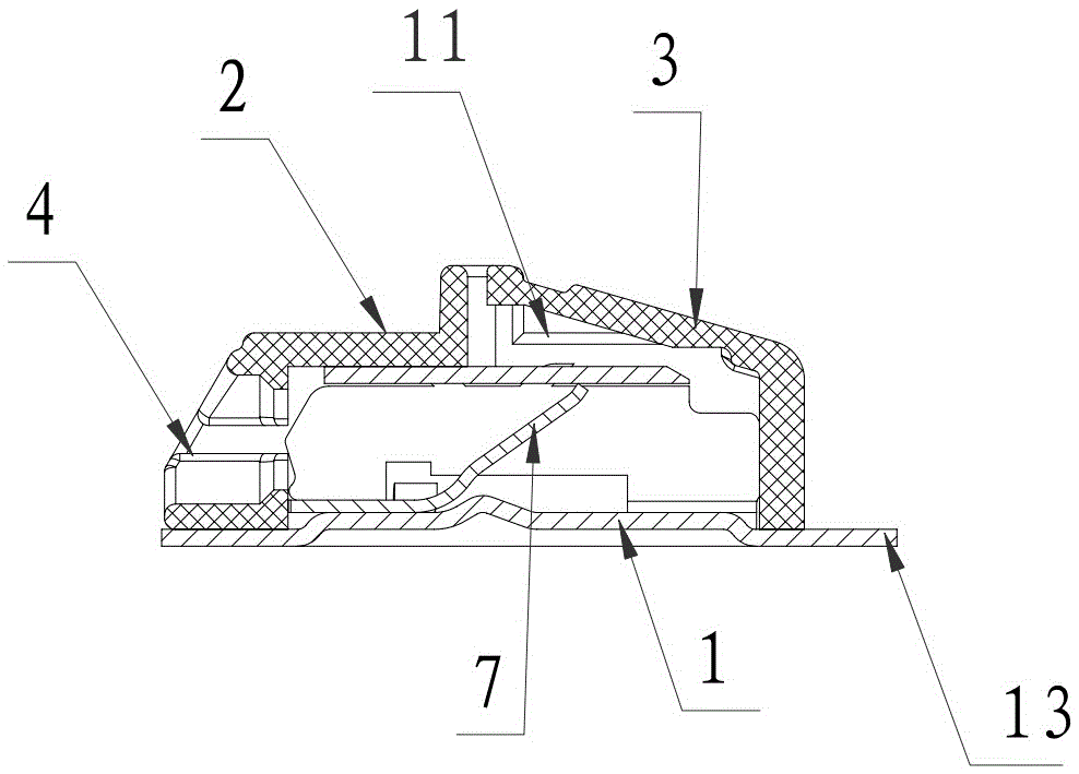
[0046] A terminal connector for LED described in Embodiment 1, such as figure 1 , figure 2 , image 3 , Figure 4 , Figure 5 , Figure 6 , Figure 7 , Figure 8 , Figure 9 , Figure 10 , Figure 11 , Figure 12 , Figure 13 and Figure 14 As shown, it includes a conductive metal clamping piece 1 arranged in the insulating housing 2 and a button 3 corresponding to the conductive metal clamping piece arranged on the insulating housing, the button and the insulating housing form an integral structure, and the front of the insulating housing is provided There is a wire socket 4 corresponding to the conductive metal clamping piece. The conductive metal clamping piece is composed of a frame-shaped wiring frame 5 and an elastic element 6 that is arranged on the frame-shaped wiring frame and cooperates with the frame-shaped wiring frame to realize clamping of the wire. The free end of the element constitutes a pointing wire 17 and cooperates with the inner top of the fr...

Embodiment 2

[0052] This embodiment 2 is improved on the basis of embodiment 1, and the specific improvement is double-strand wiring, as follows:

[0053] Such as Figure 15 , Figure 16 , Figure 17 , Figure 18 , Figure 19 , Figure 20 , Figure 21 and Figure 22 As shown, the insulating housing can be provided with two wire sockets, corresponding to the number of wire sockets in the insulating housing, two conductive metal clamping parts and two buttons are provided correspondingly.

Embodiment 3

[0055] Embodiment 3 is also improved on the basis of Embodiment 1, and the specific improvement is three-strand wire connection, as follows:

[0056] Such as Figure 23 , Figure 24 , Figure 25 , Figure 26 , Figure 27 , Figure 28 , Figure 29 and Figure 30 As shown, the insulating housing can be provided with three wire sockets, corresponding to the number of wire sockets in the insulating housing, there are three conductive metal clamping parts and three buttons are correspondingly provided. The cooperation between each conductive metal clamping piece and the button can clamp a corresponding wire separately. The use of each conductive metal clamping piece and button is not affected by other conductive metal clamping pieces and buttons. It is suitable for single Wiring of stranded and stranded conductors.


PUM


Abstract

The invention discloses a wiring terminal connector for an LED. The wiring terminal connector comprises a conductive metal clamping part, an insulating shell and a button, the button and the insulating shell form an integral structure, the insulating shell is provided with a wire insertion opening, the conductive metal clamping part is composed of a frame-shaped wiring rack and an elastic element, and the free end of the elastic element forms a clamping end and forms a driven pressing end pointing to the downward pressing end of the button; the button is composed of a pressing arm and the downward pressing end arranged at the free end of the pressing arm, the trend of the pressing arm is not matched with that of the upper surface of the insulating shell, one end of the pressing arm is connected to the upper surface of the insulating shell, the other end of the pressing arm protrudes out of the upper surface of the insulating shell, and the upper surface of the insulating shell is provided with a groove which corresponds to the position of the pressing arm and is communicated with a cavity, containing the conductive metal clamping part, of the insulating shell. On the condition that the pressing arm is assembled but not downwards pressed, the pressing arm protrudes out of the groove, the downward pressing end is not arranged in the groove, and the pressing arm is in a pre-tightening state.

Description

technical field [0001] The invention relates to a connection terminal used for LED connection, in particular to a connection terminal structure which is used in LED connection to realize simple one-time connection or one-time off-line by adopting plug-in connection. Background technique [0002] Existing LED wiring generally uses wires and terminals or connectors to be fixedly connected by nuts, screws, rivets, etc., or connected by welding. In recent years, plug-in connectors for LEDs have also appeared. The method is specifically that one or more strands of wires are connected to the plug, and another strand or more strands of wires are connected to the socket, and then the wiring is formed by plugging the plug and the socket. In this way, the structures of the existing connecting terminals continue to show various changes, and the structures of the connecting terminals are also different, as well as the degree of complexity and the way of connecting them. Although the st...

Claims


Application Information

Patent Timeline
Patent Type & Authority Applications(China)
IPC IPC(8): H01R4/48H01R9/00H01R9/24
CPCH01R9/00H01R9/24H01R4/48365
Inventor 饶小坡尹波青
Owner JIANGMEN KREALUX ELECTRICAL APPLIANCES
Why Eureka
Try Eureka