Multi-redundant inlaid wiring harness

a wiring harness and multi-redundancy technology, applied in the direction of insulated conductors, cables, instruments, etc., can solve the problem of unimportant conveyance paths, and achieve the effect of simplifying the overall wiring process and improving reliability

Inactive Publication Date: 2006-05-16
LOCKHEED MARTIN CORP
View PDF11 Cites 12 Cited by
  • Summary
  • Abstract
  • Description
  • Claims
  • Application Information

AI Technical Summary

Benefits of technology

[0006]A multi-redundant inlaid wiring harness provides for alternate electrical or optical pathways in an aircraft wiring system. A plurality or network of wires is inlaid between layers of composite fabric during fabrication of a section of an aircraft. The wires are connected at their ends to computer-controlled buses. The buses select a pathway between the buses from the number of possible pathways. If the selected pathway is later damaged, the buses select a new pathway and reroute the power or signal over the new pathway. Specifically, it is an important feature of the subject invention that the inlaid wiring network is embedded in the composite fabrication layers of the aircraft, minimizing the likelihood of shorted wiring during installation and later due to wear and tear. In addition, the controlled selection and redundancy of the wiring system improves reliability and permits on-the-fly diagnostics and correction of any faults due to a wiring failure.
[0007]The wiring system of the subject invention provides multiple pathways for the conveyance of electrical signals throughout the wiring network of the aircraft by providing required information at an entrance gateway to a conduit system, transmitting the information through the conduit system to a exit gateway and then directing the information to its destination. The system relies on the fact that as long as the information is properly entered and exited, the pathway for conveyance is unimportant. This permits any of multiple pathways to be selected and provides for built-in redundancy in the event of failure. By way of example, if certain information is required at the exit gateway and cannot be located, the first analysis would be to determine that the information was, in fact, present at the entrance gateway. Once this assurance is given, then the system will identify an available, functional path to deliver the required information to the exit gateway. This not only permits redundancy not before available in aircraft wiring systems but also simplifies the overall wiring process by tying information to its use requirements rather than to the conduits for delivering the information.

Problems solved by technology

The system relies on the fact that as long as the information is properly entered and exited, the pathway for conveyance is unimportant.

Method used


Image

  • Multi-redundant inlaid wiring harness
  • Multi-redundant inlaid wiring harness
  • Multi-redundant inlaid wiring harness

Examples


Embodiment Construction

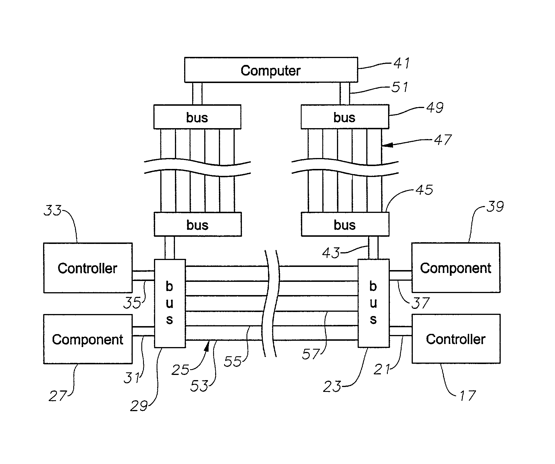
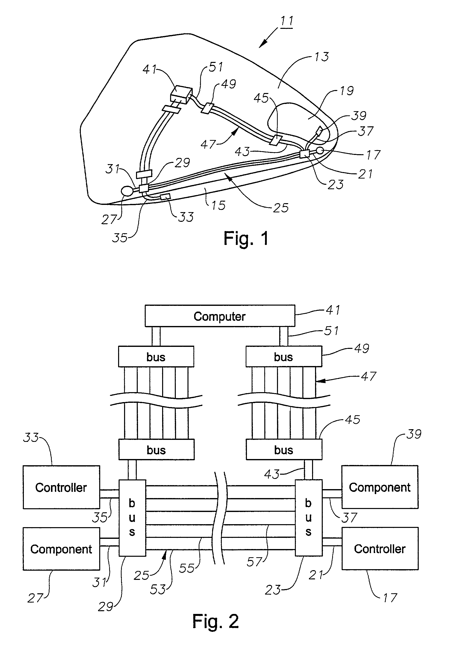
[0013]Referring to FIG. 1, aircraft 11 is a vehicle having a structure formed from layers of composite materials. Aircraft 11 is shown as a body having integrated wings and preferably being formed from a one-piece upper section 13 and a one-piece lower section 15. However, the present invention may be applied to wing sections or other vehicles and structures, including those of boats or automobiles. A cockpit controller 17 (see FIG. 2) is located in a cockpit 19 and may be a manual or automated input device for a pilot, such as a switch or a flight-control stick, or computer-controlled, such as in a fly-by-wire system or an autopilot system. Cockpit controller 17 may be an electrical controller or an optical controller. Cockpit controller 17 is connected by input wires 21 to a cockpit bus or gateway 23, cockpit bus 23 having a plurality of connectors for attaching wires 25. The terms “wire” and “wires” are used herein to denote a conduit for power or a signal, and these conduits may...


PUM

PropertyMeasurementUnit
conductiveaaaaaaaaaa
strengthaaaaaaaaaa
resistanceaaaaaaaaaa

Abstract

A multi-redundant inlaid wiring harness provides for alternate electrical or optical pathways in an aircraft wiring system. A plurality of conduits are inlaid between layers of composite fabric during fabrication of a section of an aircraft. The conduits are connected at their ends to computer-controlled gateway buses. The buses select a pathway between the buses from the number of possible pathways. If the selected pathway is later damaged, the buses select a new pathway and reroute the power or signal over the new pathway. Conduit selection is based on any of several hierarchies including path of least resistance and shortest or fastest path.

Description

BACKGROUND OF THE INVENTION[0001]1. Field of the Invention[0002]This invention generally relates to electrical system wiring in aircraft and particularly relates to redundant wiring systems inlaid in a composite body.[0003]2. Description of the Prior Art[0004]Electrical power connections in aircraft are typically accomplished using wiring networks made from a conductive material such as metal, whereas control signals may be transmitted using metal wires or optical fibers. Many wires are bundled together in a harness for ease of installation and replacement and to facilitate protection of the wires. The harnesses are located within the interior of the aircraft and may have a single, multiple wire connector at either or both ends, or wires can be separated from the harness as needed along the length of the harness.[0005]Composite materials are being used to construct sections of aircraft, though their use has generally been limited to wing surfaces and exterior panels. Methods of cons...

Claims


Application Information

Patent Timeline
Patent Type & Authority Patents(United States)
IPC IPC(8): G06F13/00B64D43/00G02B6/43
CPCG02B6/43B64D43/00
Inventor CARPENTER, BILLY R.
Owner LOCKHEED MARTIN CORP
Why Eureka
Try Eureka