
Side airbag device

A technology of side airbags and airbags, applied in transportation and packaging, pedestrian/passenger safety arrangements, vehicle components, etc., can solve problems such as difficult to limit the direction of deployment

Active Publication Date: 2016-06-08
MAZDA MOTOR CORP +1
View PDF9 Cites 8 Cited by
  • Summary
  • Abstract
  • Description
  • Claims
  • Application Information

AI Technical Summary

Problems solved by technology

Since there is only a small gap between the occupant and the door, it may be difficult to inflate the lower end of the airbag into a desired shape if the lower end of the airbag is largely inflated before being deployed toward the side of the occupant's abdomen.
[0007] In addition, in the case of a side air bag deployed from the side of the seat, the side air bag flying out from the side of the seat may hit the door or The column is deployed toward the occupant side by means of its reverse movement, and it is difficult to limit the direction of deployment

Method used


Image

  • Side airbag device
  • Side airbag device
  • Side airbag device

Examples


Embodiment Construction

[0039] {implementation method}

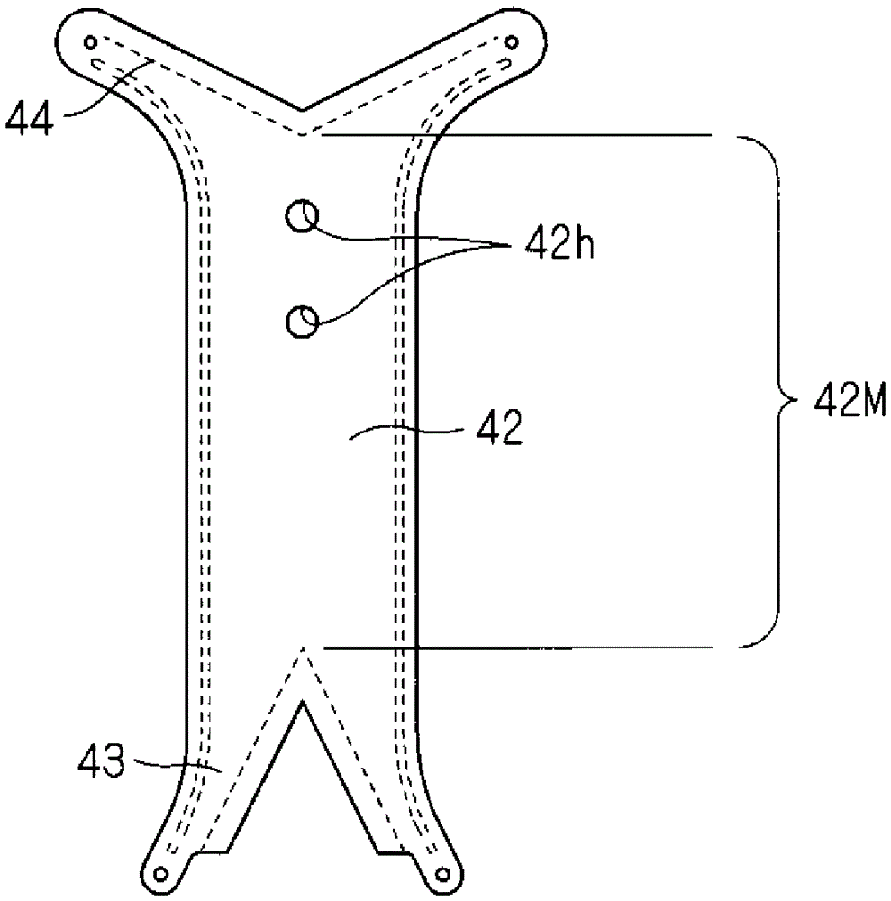
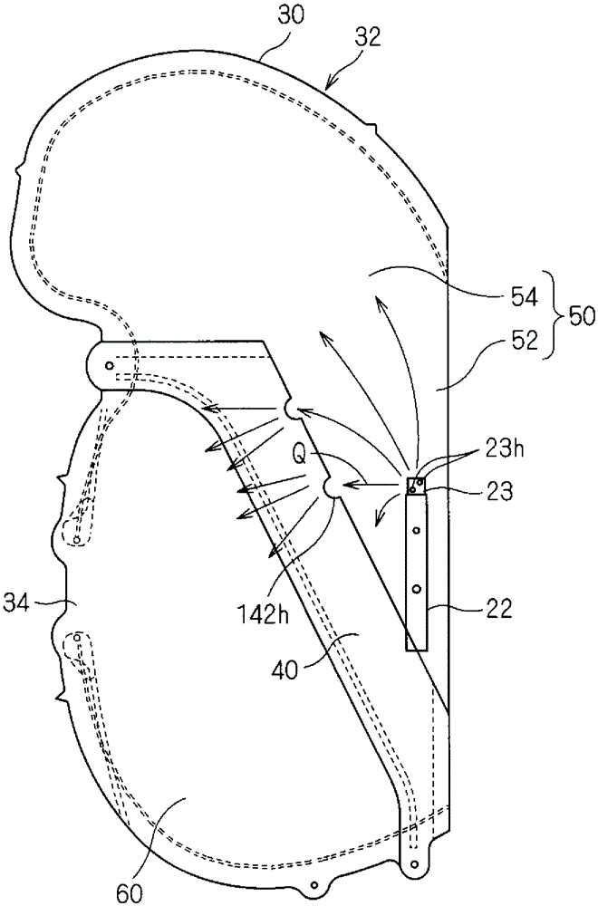
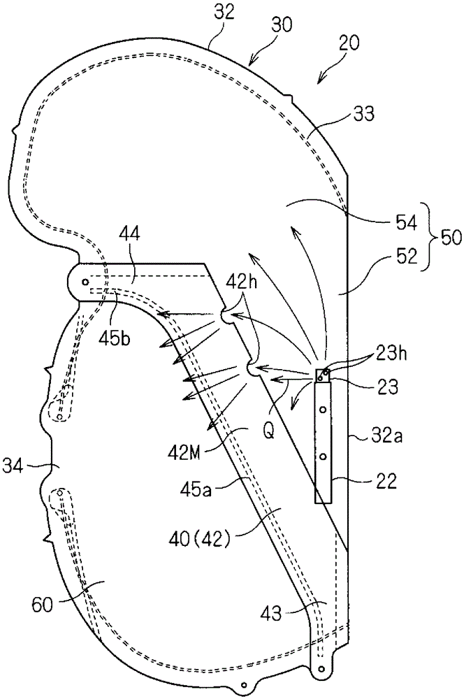
[0040] Hereinafter, a side airbag device according to an embodiment will be described. figure 1 It is a schematic side view showing a state in which the side airbag device 20 according to the embodiment is installed in the vehicle seat 10 , figure 2 is a schematic side view of the side airbag device 20, image 3 yes figure 2 A schematic cross-sectional view of line III-III, Figure 4 yes figure 2 A schematic cross-sectional view of line IV-IV. In addition, in the schematic side view of the side airbag device 20 , internal structural parts may also be indicated by solid lines.

[0041] The side airbag device 20 is configured to be attachable to the vehicle seat 10 .

[0042] The vehicle seat 10 includes a seat portion 12 , a back portion 14 , and a headrest portion 16 . As the vehicle seat 10, a driver's seat, a passenger's seat, or the like of a vehicle is assumed.

[0043]On the side of one side of the vehicle seat 10 , for example,...


PUM


Abstract

The purpose of the present invention is to provide a side airbag device which is configured so that the entire airbag can be promptly and accurately expanded to a correct position and so that the entire airbag can be inflated into a desired shape after the expansion. A side airbag device can be mounted in a seat side section of a vehicle and comprises: a long-shaped inflator (22); and an airbag including an inflatable bag-like section (20) and a partition section (for example, a partition wall section (40)) which divides the bag-like section (20) into a first gas chamber (50) and a second gas chamber (60). The first gas chamber (50) includes: a supporting inflation section (52) which can be expanded into a shape which gradually expands from the lower end to the upper end along the seat side section; and a protective inflation section (54) which can be expanded on the other end side of the supporting inflation section (52). The inflator (22) is disposed so as to be capable of supplying gas into the supporting inflation section (52). At least one gas flow hole (42h) is provided in the portion of the partition section, which separates the second gas chamber (60) and the supporting inflation section (52) of the first gas chamber (50). The second gas chamber (60) is provided below the first gas chamber (50).

Description

technical field [0001] The present invention relates to a side airbag device incorporated in a side portion of a seat of a vehicle. Background technique [0002] Patent Document 1 discloses a side airbag provided on a vehicle outer side portion of a seat back of a vehicle seat. [0003] Inside the side airbag, a first flow path and a second flow path are formed. The first flow path allows the gas ejected from the gas outlet of the inflator to flow to the upper portion of the airbag that protects the occupant's head side, The second flow path allows gas to flow from the upper portion of the airbag to the lower portion of the airbag that protects the chest side of the occupant. The airbag has a structure in which gas is flowed from the inflator into the first flow path during a side collision of the vehicle to inflate and expand the upper portion of the airbag toward the side of the head, and at the same time, gas is flowed into the second airbag from the upper portion of the...

Claims


Application Information

Patent Timeline
IPC IPC(8): B60R21/207B60R21/2338B60R21/239
CPCB60R21/239B60R21/23138B60R2021/23146B60R2021/23324B60R21/2346B60R21/207B60R21/233B60R21/261B60R2021/0006B60R2021/0032
Inventor 椙村勇一柴原多卫冈田慎治星野雅人东英孝佐佐木航冈上喜贵
Owner MAZDA MOTOR CORP
Learn More