
multilateral overflow system

A multilateral overflow and bypass overflow technology, applied in the field of hydraulic systems, can solve the problem that the bandwidth of the shock absorber cannot meet the requirements of the fluid pulsation frequency

Active Publication Date: 2017-10-31
BEIHANG UNIV
View PDF6 Cites 0 Cited by
  • Summary
  • Abstract
  • Description
  • Claims
  • Application Information

AI Technical Summary

Problems solved by technology

Therefore, the bandwidth of the shock absorber cannot meet the increasing frequency requirements of fluid pulsation in hydraulic systems, which has become a bottleneck in the application of traditional fluid pulsation active control methods based on the principle of bypass overflow in high-speed hydraulic systems.

Method used


Image

  • multilateral overflow system
  • multilateral overflow system
  • multilateral overflow system

Examples


Embodiment Construction

[0022] Embodiments of the present application are described below with reference to the drawings. Elements and features described in one drawing or one embodiment of the present application may be combined with elements and features shown in one or more other drawings or embodiments. It should be noted that representation and description of components and processes that are not relevant to the present application and known to those of ordinary skill in the art are omitted from the drawings and descriptions for the purpose of clarity.

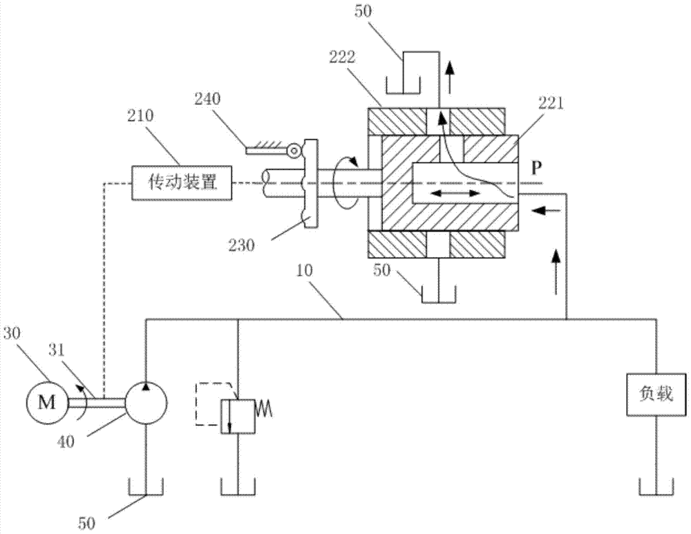
[0023] see figure 1 Shown is a structural diagram 100 of an embodiment of the multilateral overflow system of the present application.

[0024] The multilateral overflow system of this embodiment includes a main oil passage 10 and a cam disc type multilateral overflow pulsation attenuation control system.

[0025] Wherein, the cam disc type multilateral overflow pulsation attenuation control system includes a transmission device 210 , a multil...


PUM


Abstract

The invention relates to a multilateral overflow system. The multilateral overflow system comprises a main oil fluid channel and a cam plate type multilateral overflow pulsation attenuation control system. The cam plate type multilateral overflow pulsation attenuation control system comprises a transmission device, a multilateral overflow valve, a cam plate and a cam lever. The multilateral overflow valve comprises a valve core and a valve core sleeve so that at least one bypass overflow inlet and at least one bypass overflow outlet can be made to communicate to form an overflow channel. The transmission device is used for driving the valve core to rotate around a rotating shaft. The cam plate is matched with the cam lever so that the relative positions of the valve core and the valve core sleeve can be adjusted. According to the scheme of the multilateral overflow system, the overflow inlets and the overflow outlets are matched to form the overflow channel by controlling movement of the valve core, and flow pulsation produced in a main pipeline can be at least partially offset.

Description

technical field [0001] The application relates to the field of hydraulic systems, in particular to a multilateral overflow system. Background technique [0002] The hydraulic system has been widely used in many important industrial sectors such as aviation, spaceflight, and shipbuilding due to its advantages of high power density and high rigidity against load. With the development of hydraulic systems in the direction of high speed, high pressure, and high power, the vibration and noise problems of hydraulic energy pipeline systems are becoming more and more serious, which has become a bottleneck restricting the development of hydraulic systems in the direction of high pressure and low noise. [0003] At present, most hydraulic systems use axial piston pumps to provide hydraulic energy, because axial piston pumps have the advantages of high output pressure, high work efficiency and high reliability. However, the axial piston pump will inevitably produce fluid pulsation due...

Claims


Application Information

Patent Timeline
Patent Type & Authority Patents(China)
IPC IPC(8): F15B21/04F16L55/055
CPCF15B21/001F15B21/044F15B2211/8606F16L55/055
Inventor 尚耀星汤洪焦宗夏徐远志吴帅
Owner BEIHANG UNIV
Learn More