Gyro flywheel system-based two dimensional spacecraft angular rate measurement method

A gyro flywheel and measurement method technology, applied in the field of inertial navigation, to achieve the effect of avoiding dynamic calibration and high angular rate measurement accuracy

Inactive Publication Date: 2016-06-15
HARBIN INST OF TECH
View PDF4 Cites 4 Cited by
  • Summary
  • Abstract
  • Description
  • Claims
  • Application Information

AI Technical Summary

Problems solved by technology

[0005] The present invention studies the precise measurement of the two-dimensional spacecraft angular rate by the gyro flywheel system in the working state of the rotor with a large tilt angle. Spacecraft Angular Rate Measurement Accuracy

Method used


Image

  • Gyro flywheel system-based two dimensional spacecraft angular rate measurement method
  • Gyro flywheel system-based two dimensional spacecraft angular rate measurement method
  • Gyro flywheel system-based two dimensional spacecraft angular rate measurement method

Examples


specific Embodiment approach 1

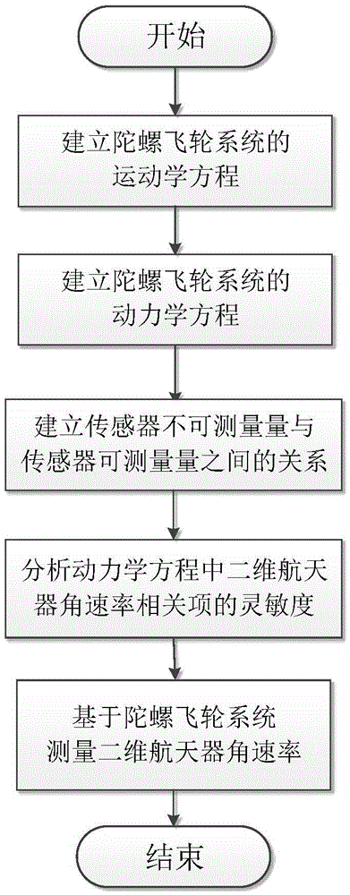
[0022] Specific implementation mode one: the method for measuring the angular rate of the two-dimensional spacecraft based on the gyro flywheel system in this implementation mode is implemented according to the following steps:

[0023] Step 1, establishing the kinematic equation of the gyro flywheel system;

[0024] Step 2, establishing the dynamic equation of the gyro flywheel system;

[0025] Step 3, establishing the relationship between the unmeasurable quantity of the sensor and the measurable quantity of the sensor;

[0026] Step 4, analyzing the sensitivity of the two-dimensional spacecraft angular rate related items in the dynamic equation;

[0027] Step 5. Measure the angular rate of the two-dimensional spacecraft based on the gyro flywheel system.

specific Embodiment approach 2

[0028] Specific embodiment two: the difference between this embodiment and specific embodiment one is: it is characterized in that, described step one establishes the kinematic equation of gyroscope flywheel system and realizes according to the following steps:

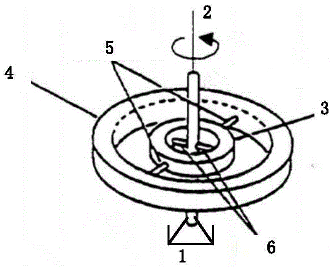
[0029] Such as figure 2 As shown, the core components of the gyro flywheel system are composed of a housing 1, a motor shaft 2, a balance ring 3, a rotor 4, an outer flexible shaft 5, and an inner flexible shaft 6, wherein the motor shaft 2 is connected to the inner flexible shaft 6 through a pair of The inner side of the gimbal 3 is connected, the outer side of the gimbal 3 is connected to the inner side of the rotor 4 through a pair of outer flexible shafts 5, and the inner flexible shaft 6 is kept orthogonal to the outer flexible shaft 5; , and the body coordinate system of the rotor are respectively Ox c the y c z c , Ox m the y m z m , Ox g the y g z g , Ox r the y r z r , the relative angular positi...

specific Embodiment approach 3

[0041] Specific embodiment three: this embodiment is different from specific embodiment one or two: it is characterized in that, described step 2 establishes the dynamic equation of gyroscope flywheel system and realizes according to the following steps:

[0042] Step 21, constructing the energy equation of the gyro flywheel system;

[0043] The kinetic energy T of the gyro flywheel system is composed of three parts: the motor shaft, the balance ring and the rotor. For example, the generalized velocity quadratic form of the kinetic energy T in formula (4) is expressed as:

[0044] T = 1 2 ( Σ i = x , y , z I m i ω m ...


PUM


Abstract

The invention relates to a gyro flywheel system-based two dimensional spacecraft angular rate measurement method, and belongs to the field of inertial navigation. The gyro flywheel system-based two dimensional spacecraft angular rate measurement method is provided to solve the two dimensional spacecraft angular rate measurement problem by using the rotor large-roll angle working state of a gyro flywheel. The method comprises the following steps: 1, establishing the kinematical equation of a gyro flywheel system; 2, establishing the kinetic equation of the gyro flywheel system; 3, establishing a relationship between the immeasurable amount of a sensor and the measurable amount of the sensor; 4, analyzing the sensitivity of the contiguous item of the two dimensional spacecraft angular rate in the kinetic equation; and 5, measuring the two dimensional spacecraft angular rate based on the gyro flywheel system. The method is suitable for controlling and measuring the spacecraft attitude.

Description

technical field [0001] The invention is a method for measuring the angular rate of a two-dimensional spacecraft based on a gyro flywheel system, and specifically relates to the field of inertial navigation. Background technique [0002] The gyro flywheel system is developed based on a dynamically tuned gyroscope, which can be used as both an actuator and a sensor in the attitude control system of a spacecraft. As an actuator, the gyro flywheel system can output three-axis control torque through the motor speed regulation of the gyro flywheel system and the two-dimensional radial tilting motion of the rotor. At the same time, the gyro flywheel system can realize two-dimensional aerospace The device angular rate measurement function. [0003] At present, the main idea of ​​realizing the angular rate measurement function of two-dimensional spacecraft based on the three-dimensional torque output of the gyro flywheel system is as follows: (1) The kinematic equation and the dynam...

Claims


Application Information

Patent Timeline
Patent Type & Authority Applications(China)
IPC IPC(8): G01C19/42
CPCG01C19/42
Inventor 刘晓坤赵辉赵清霍鑫史维佳姚郁
Owner HARBIN INST OF TECH
Why Eureka
Try Eureka