Residual current protector

A residual current and protector technology, applied in the field of circuits, can solve problems such as the failure of the residual current protector to work normally, the inconvenience of management, maintenance and inspection, and the failure of the residual current protector.

Active Publication Date: 2016-06-15
SOOAR TIANJIN ELECTRICAL EQUIP CO LTD
View PDF6 Cites 8 Cited by
  • Summary
  • Abstract
  • Description
  • Claims
  • Application Information

AI Technical Summary

Problems solved by technology

[0003] However, when checking the residual current protector, it needs to trip to temporarily interrupt the grid power supply, which is very inconvenient for ordinary users
Therefore, in many cases, the inspection of the residual current protector will be forgotten or ignored, which greatly increases the hidden danger of the residual current protector.
[0004] Conventional residual current protectors with residual current inspection function can only qualitatively inspect whether the residual current protection function is normal, but cannot quantitatively inspect the operation accuracy of residual current protection
[0005] Conventional residual current measurement function calibration is often only performed when the residual current protector leaves the factory, and standard signals need to be injected separately during execution, which increases circuit complexity and cumbersome operation process
[0006] In addition, once the key parts of the residual current protector are damaged, the function of the residual current protector will be lost immediately. The conventional residual current inspection function does not have real-time performance. Before the problem is discovered, the residual current protector may not work normally. Will cause the residual current protector to fail in many electric shock accidents
[0007] Most of the current residual current protectors are produced, sold and used in the form of independent individuals. They have no connection with each other, cannot carry out information communication, are inconvenient for management, maintenance and inspection, and are not conducive to safe, reliable and efficient power consumption.

Method used


Image

  • Residual current protector
  • Residual current protector
  • Residual current protector

Examples


Embodiment Construction

[0014] Characteristics of various aspects of the invention and exemplary embodiments are now described in detail, and in the following detailed description, numerous specific details are set forth in order to provide a thorough understanding of the invention. It will be apparent, however, to one skilled in the art that the present invention may be practiced without some of these specific details. The following description of the embodiments is only to provide a better understanding of the present invention by showing examples of the present invention.

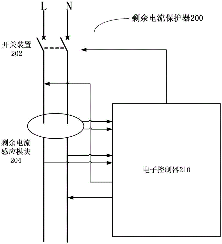
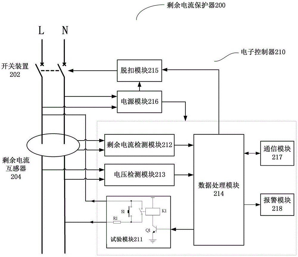
[0015] The residual current protector is an important low-voltage protective device, which is mainly used to protect the electrical equipment when there is a residual current fault and when there is a fatal electric shock to the person. Therefore, the reliability requirements of the residual current protector are relatively high. It is necessary to check whether its working characteristics are normal before putting it into use,...


PUM


Abstract

The invention discloses a residual current protector, which comprises a switch device, a residual current transformer and an electronic controller, wherein the electronic controller detects a network voltage, generates a simulated residual current in a power network and controls off and on of the switch device on the basis of an actual residual current, sensed by the residual current transformer, in the power network before the simulated residual current is generated, and the total residual current and network voltage, sensed by the residual current transformer, in the power network after the simulated residual current is generated. By the technical scheme disclosed by the invention, inspection of the residual current protection function can be achieved under the condition of not interrupting power supply; the protection capability of the residual current protector is ensured; and the burden of a user is relieved.

Description

technical field [0001] The present invention relates to the field of circuits, and more particularly to a residual current protector. Background technique [0002] The residual current protector is an important low-voltage protective device, which is mainly used to disconnect the grid power supply in the event of a residual current fault in the equipment or in the event of a fatal electric shock to protect personal safety. Therefore, the reliability requirements of the residual current protector are relatively high. It is necessary to check whether its working characteristics are normal before putting it into use, and to check the reliability of its protection action regularly during use. [0003] However, when checking the residual current protector, it needs to trip to temporarily interrupt the grid power supply, which is very inconvenient for ordinary users. Therefore, in many cases, the inspection of the residual current protector will be forgotten or ignored, which gre...

Claims


Application Information

Patent Timeline
Patent Type & Authority Applications(China)
IPC IPC(8): H02H3/32
CPCH02H3/32
Inventor 兰利民南寅赵志群张太利
Owner SOOAR TIANJIN ELECTRICAL EQUIP CO LTD
Why Eureka
Try Eureka