Electrical cabinet with power device fixing device

A technology of fixing devices and electrical cabinets, which is applied in the field of electric power, can solve problems such as complicated installation, inconvenient disassembly and assembly, and large amount of shaking, so as to achieve the effects of avoiding interference, ensuring positioning stability, and convenient locking and unlocking

Inactive Publication Date: 2016-06-15
晋江市晋美日用品有限公司
View PDF5 Cites 0 Cited by
  • Summary
  • Abstract
  • Description
  • Claims
  • Application Information

AI Technical Summary

Problems solved by technology

Some existing installation methods are either complicate

Method used


Image

  • Electrical cabinet with power device fixing device
  • Electrical cabinet with power device fixing device
  • Electrical cabinet with power device fixing device

Examples


Example Embodiment

[0010] Combine below Figure 1-4 The present invention will be described in detail.

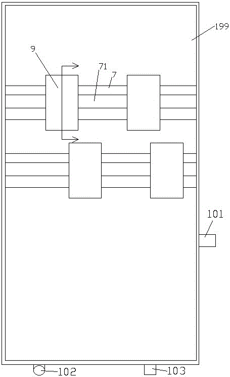
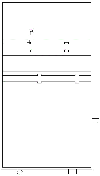
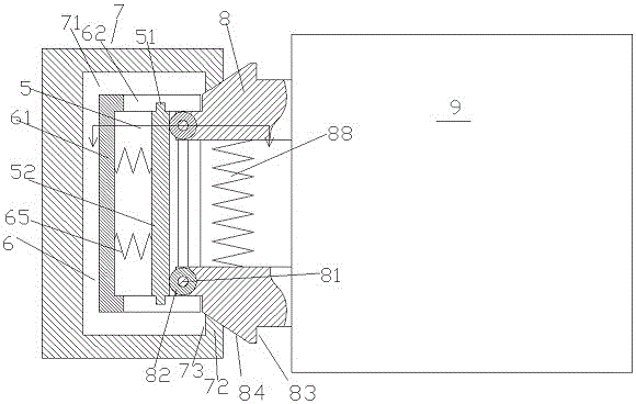
[0011] An electrical cabinet with a power device fixing device according to an embodiment of the present invention is used to fixly install the power device 9 in the electrical cabinet 199, including a fixed beam 7 fixed in the electrical cabinet 199 and a The elastic clamping assembly connected to the inner end of the device 9, wherein the elastic clamping assembly includes two wedge-shaped clamping blocks 8 arranged symmetrically, and a pressing expansion spring 88 is arranged between the two wedge-shaped clamping blocks 8 In order to elastically expand the two wedge-shaped blocks 8 described above, each wedge-shaped block 8 has a wedge-shaped surface 84 on the outside, and a side end of the wedge-shaped surface close to the fixed beam 7 passes through a fixed shaft 81. A roller 82 is hinged, and the fixed shaft 81 extends beyond the two extensions 811 of the end to slidably engage with the s...


PUM


Abstract

The invention provides an electrical cabinet with a power device fixing device, and is used for fixedly installing power devices (9) in the electrical cabinet (199). The electrical cabinet comprises fixing beams (7) which are fixed in the electrical cabinet (199) and elastic clamping components which are connected with the internal ends of the power devices (9). Each elastic clamping component comprises two wedge clamp blocks (8) which are symmetrically arranged. An abutting open spring (88) is arranged between the two wedge clamp blocks (8) and used for elastically shoving the two wedge clamp blocks (8) apart. The external side of each wedge clamp block (8) is provided with a wedge surface (84), and the end part of one side, which is close to the fixing beams (7), of the wedge surface is provided with a roller (82) in a hinged way through a fixing shaft (81).

Description

technical field [0001] The invention relates to the field of electric power, in particular to an electric cabinet with a fixing device for electric devices. Background technique [0002] Power electrical devices often need to be fixed and installed with good firmness in the electrical cabinet. However, these devices often need to be replaced for maintenance and maintenance. Therefore, it is desired to have a fast installation and disassembly installation method in the occasion where convenient disassembly is required. At the same time, its positioning state after installation needs to have good position stability to ensure safe wiring and stable operation. Some existing installation methods are either relatively complicated to install and inconvenient to disassemble or assemble; or their fixed positioning is relatively low in firmness and has a relatively large amount of shaking. Contents of the invention [0003] The purpose of the present invention is to provide an el...

Claims


Application Information

Patent Timeline
IPC IPC(8): H05K7/14
CPCH05K7/1405
Inventor 范翠贞
Owner 晋江市晋美日用品有限公司
Why Eureka
Try Eureka