Three-degree-of-freedom coaxial output mechanism

A technology with coaxial output and degrees of freedom, applied in manipulators, program-controlled manipulators, manufacturing tools, etc., can solve problems such as difficulty in meeting high-speed and high-acceleration, large inertia of moving parts, and limitations of dynamic characteristics, and achieve simple structure and rotation. The effect of small inertia and relatively small size of the mechanism

Inactive Publication Date: 2016-06-22
TIANJIN UNIV
View PDF7 Cites 2 Cited by
  • Summary
  • Abstract
  • Description
  • Claims
  • Application Information

AI Technical Summary

Problems solved by technology

At present, the research on this type of robot mechanism is more and more extensive at home and abroad. The US patent document US4392776, the European patent document EP0169473 and the Chinese patent document CN1779936 all involve a SCARA robot mechanism with three or four degrees of freedom. This type of robot mechanism It mainly includes the frame, driving parts, active arm, driven arm and moving platform. Although this type of robot mechanism can realize a full circle rotation in the motion plane, because the mechanism itself adopts an open-loop structure, the active and driven The inertia of the arm is large, and its dynamic characteristics are limited under high-speed and high-acceleration conditions
For this reason, the Chinese patent document CN101973030 proposes a parallel robot mechanism that can realize full-circle rotation, but the drive of the third near-frame rod is directly driven by the motor and reducer installed on the rotating body, and the inertia of the moving parts is relatively large. It is also difficult to meet the requirements of high-speed and high-acceleration conditions

Method used


Image

  • Three-degree-of-freedom coaxial output mechanism
  • Three-degree-of-freedom coaxial output mechanism
  • Three-degree-of-freedom coaxial output mechanism

Examples


Embodiment Construction

[0011] In order to further understand the content, features and effects of the present invention, the following embodiments are given as examples, and detailed descriptions are as follows with accompanying drawings:

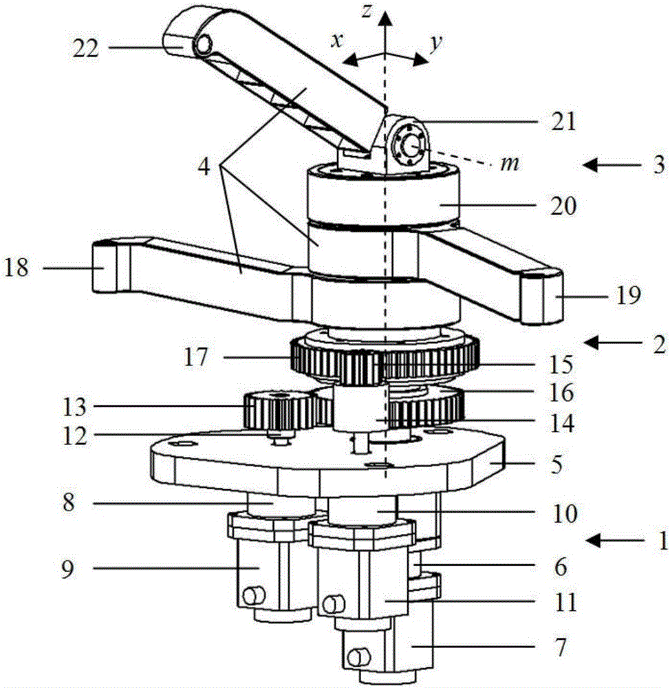
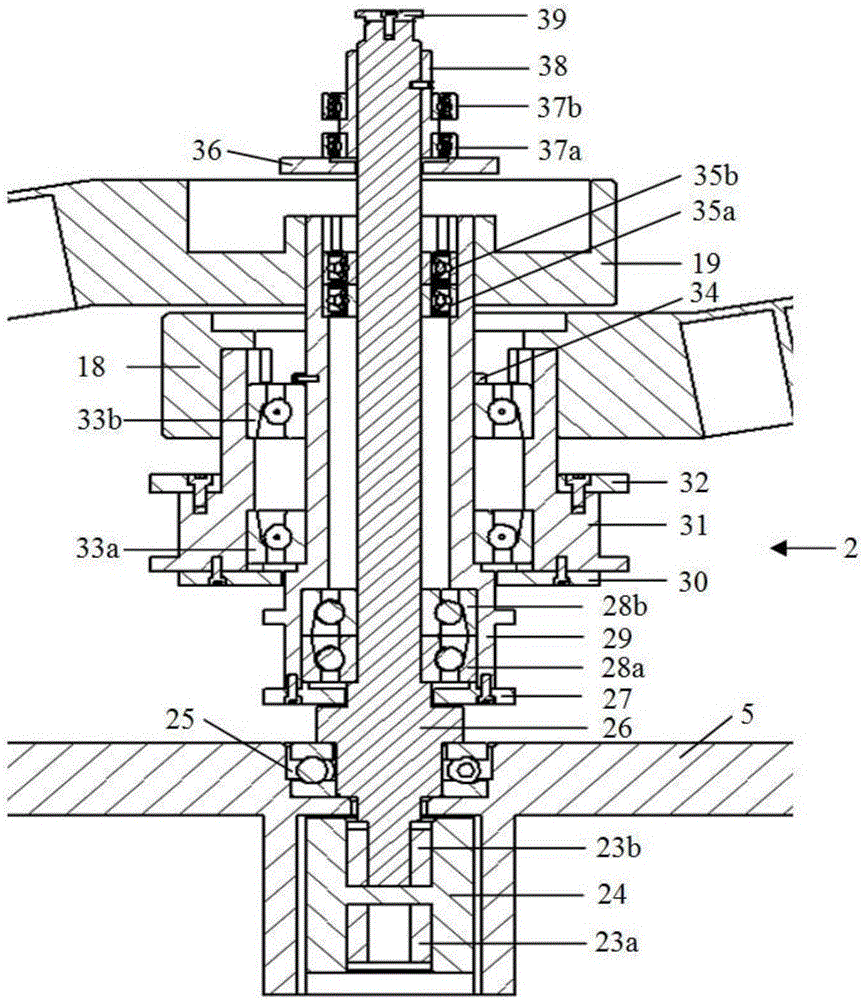
[0012] See Figure 1 ~ Figure 3 , A three-degree-of-freedom coaxial output mechanism, including a vertically arranged central transmission shaft 26, the central transmission shaft 26 is supported by a horizontally arranged base 5 and driven by a first motor 7.

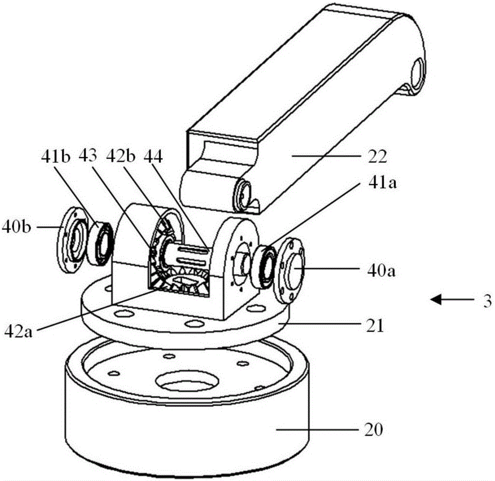
[0013] A first hollow shaft 29, a follower 20, and a driving bevel gear 42a are installed on the central transmission shaft 26. The first hollow shaft 29 and the follower 20 are axially fixed and circumferentially rotatably installed. On the central transmission shaft 26, the driving bevel gear 42a is fixedly mounted on the central transmission shaft 26; a bevel gear support 21 is fixedly mounted on the follower 20, and on the bevel gear support 21 A first driving arm rotation shaft 44 is supported. A driven b...


PUM


Abstract

The invention discloses a three-degree-of-freedom coaxial output mechanism, which includes a vertically arranged central transmission shaft, which is supported by a horizontally arranged base and driven by a first motor; a first hollow shaft is installed on the central transmission shaft Shaft, follower seat and driving bevel gear; a bevel gear support is fixed on the follower seat, the first active arm shaft is supported on the bevel gear support, and the driven cone is fixed on the first main arm shaft The gear and the first driving arm, the driven bevel gear meshes with the driving bevel gear; the second hollow shaft, the first large gear and the second driving arm are installed on the first hollow shaft, and the first large gear meshes with the first small gear , the first small gear is driven by the second motor; the third active arm and the second large gear are fixedly installed on the second hollow shaft, the second large gear meshes with the second small gear, and the second small gear is driven by the third motor . The moment of inertia of the moving part of the invention is relatively small, and has high speed and high acceleration capability.

Description

Technical field [0001] The invention relates to a robot mechanism, in particular to a high-speed robot mechanism capable of realizing full-circle rotation. Background technique [0002] The use of robotic mechanisms in automated sorting, packaging and logistics production lines in the food, electronics, and pharmaceutical industries is becoming more and more popular. This type of robotic mechanism mainly realizes the grasping and placing of objects and large-scale rapid movement. At present, research on this type of robot mechanism is becoming more and more extensive at home and abroad. The US patent document US4392776, the European patent document EP0169473 and the Chinese patent document CN1779936 all involve a three- or four-degree-of-freedom SCARA robot mechanism. This type of robot mechanism It mainly includes the frame, drive components, active arm, driven arm, and moving platform. Although this type of robot mechanism can realize a full circle rotation in the motion plane,...

Claims


Application Information

Patent Timeline
IPC IPC(8): B25J9/10B25J9/04
CPCB25J9/102B25J9/042B25J9/108
Inventor 臧家炜梅江平谢胜龙薛娜曾侠乔正宇
Owner TIANJIN UNIV
Why Eureka
Try Eureka