Annular lifting tool

A spreader and ring technology, applied in the direction of load hanging components, transportation and packaging, can solve the problems of many structural components, complex assembly, asymmetry, etc., and achieve the effect of improving the safety factor, facilitating adjustment, and increasing the included angle.

Inactive Publication Date: 2016-06-22
WUXI FORMEN TECHN
View PDF0 Cites 5 Cited by
  • Summary
  • Abstract
  • Description
  • Claims
  • Application Information

AI Technical Summary

Problems solved by technology

The problem with this structure is that since the lifting lugs 5 are respectively fixed at the three vertices of the triangular connector 1, the positions of the lifting lugs cannot be adjusted. It is often asymmetrical, and the liftin

Method used


Image

  • Annular lifting tool
  • Annular lifting tool

Examples


Embodiment Construction

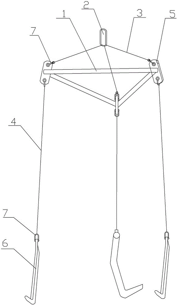
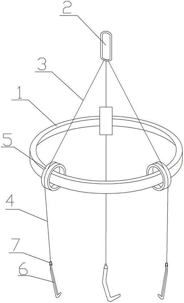
[0011] Such as figure 2 As shown, the present invention includes an annular connector 1, a suspension ring 2, an upper sling 3, a lower sling 4, a roller 5, and a hook 6. There are three upper slings and lower slings 4 respectively, and the roller 5 is movably socketed on the annular connector. 1, there is a gap between the inner ring of the roller 5 and the outer wall of the annular connector 1, so that the roller 5 can move anywhere on the annular connector 1, and the lower end of the upper sling 3 surrounds the outer wall of the roller 5 to hang The lower end of the cable 3 wraps around the roller 5 and then extends to the lower sling 4 for hanging. The height needs to be adjusted arbitrarily, and the consistency during work is enhanced; the lower end of the lower sling 4 and the hook 6 are connected through a shackle 7 .


PUM


Abstract

The invention discloses an annular lifting tool. The lifting tool can reliably lift work pieces, and is simple in structure and high in uniformity when the entire lifting tool operates. The lifting tool comprises lifting rings, upper suspension cables, lower suspension cables, and hooks, wherein three upper suspension cables and three lower suspension cables are arranged; the upper ends of the upper suspension cables are connected with the lifting rings; and the lower ends of the lower suspension cables are connected with the hooks. The lifting tool is characterized in that the lower ends of the upper suspension cables are connected with annular connecting elements through rollers; the upper ends of the lower suspension cables are connected with the annular connecting elements through the rollers; and the rollers are in movable connection with the annular connecting elements.

Description

technical field [0001] The invention relates to a hoisting sling, which is mainly used for hoisting ring-shaped or circular workpieces, in particular to a ring-shaped sling. Background technique [0002] The existing spreader for hoisting annular or circular workpieces is a triangular spreader, see figure 1 , including triangular connector 1, ring 2, upper sling 3, lower sling 4, lifting lug 5, hook 6, the connection between the upper and lower sling and the lifting lug and the lower sling and the hook are all through shackle 7 , when in use, the suspension ring 2 is hung on the hook of the crane, and the hook 6 is fixed on the ring or circular workpiece. The problem with this structure is that since the lifting lugs 5 are respectively fixed at the three vertices of the triangular connector 1, the positions of the lifting lugs cannot be adjusted. It is often asymmetrical, and the lifting lugs at fixed positions may not be able to adapt. Moreover, there are many existing st...

Claims


Application Information

Patent Timeline
IPC IPC(8): B66C1/14
Inventor 田芸
Owner WUXI FORMEN TECHN
Why Eureka
Try Eureka