Air cylinder with liquid buffer device

A buffer device and cylinder technology, applied in the direction of fluid pressure actuation device, etc., can solve the problems of piston and piston rod damage to cylinder, etc., and achieve the effect of slowing down collision and impact, high efficiency and simple structure

Active Publication Date: 2016-06-22
ZHEJIANG UNIV OF TECH
View PDF5 Cites 2 Cited by
  • Summary
  • Abstract
  • Description
  • Claims
  • Application Information

AI Technical Summary

Problems solved by technology

[0003] In order to overcome the defect that the piston and the piston rod will damage the cylinder when the high-speed cylinder is running in the prior art, the invention provides a liquid buffer device in the cylinder

Method used


Image

  • Air cylinder with liquid buffer device
  • Air cylinder with liquid buffer device
  • Air cylinder with liquid buffer device

Examples


Embodiment Construction

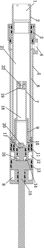
[0022] Such as figure 1 As shown, take the end where the thick piston rod 2 is located (ie the top in the figure) as the left direction, and the end where the thin piston rod 15 is located (ie the bottom in the figure) as the right direction.

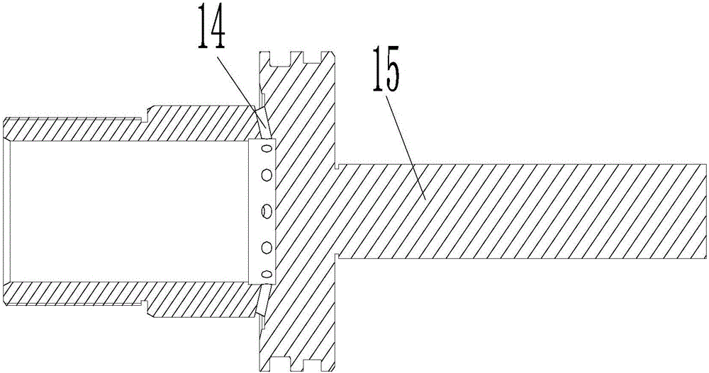
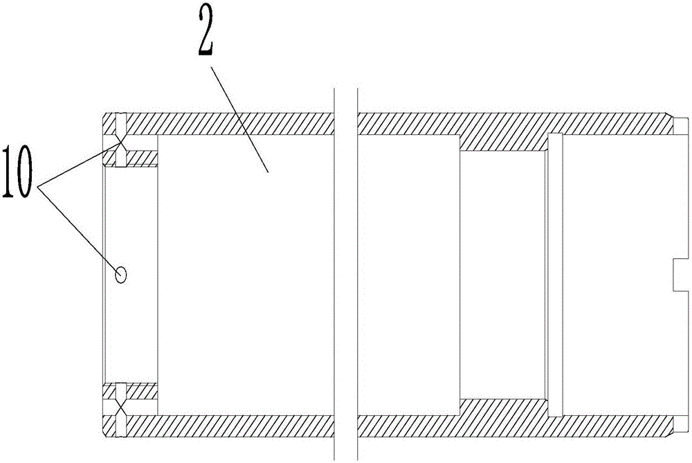
[0023] as attached Figure 1-3 As shown, a cylinder with a liquid buffer device includes a cylinder body 5 and a piston rod group slidably arranged in the cylinder body 5, and the piston rod group includes a thick piston rod 2 and a thin piston rod that are matched in thickness 15. The outer end of the thick piston rod 2 passes through the left end cover 3 of the cylinder body 5, the outer end of the thin piston rod 15 passes through the right end cover of the cylinder body 5, and the hollow thick piston rod 2 has an airtight first air cavity 21 , the inner end of the thin piston rod 15 passes through the inner end of the thick piston rod 2 and extends toward the first air cavity 21, and the thin piston rod 15 and the thick piston rod ...


PUM


Abstract

The invention relates to an air cylinder with a liquid buffer device. The air cylinder is characterized in that the outer end of a thick piston rod passes through a left end cover of a cylinder body; the outer end of a thin piston rod passes through a right end cover of the cylinder body; the buffer device for reducing the operation speed of a piston rod set is arranged between the thick piston rod and the thin piston rod; a first piston and the left end cover define a second air cavity surrounding the thick piston rod in the cylinder body; a second piston and the first piston define a first liquid cavity surrounding the thin piston rod in the cylinder body; an air inlet cavity for pushing the thin piston rod to slide is formed in the right end of the cylinder body; a third piston divides a hollow inner cavity into a second liquid cavity and a connecting chamber in an airtight way; the second liquid cavity is communicated with the first liquid cavity through a third through hole formed in the thin piston rod; the connecting chamber of the thin piston rod is communicated with a sleeve inner cavity through an inner port of the thin piston rod to form an airtight third air cavity; a spring is arranged in the third air chamber in the axial direction, one end of the spring sleeves a positioning shaft on the inner end surface of the sleeve, and the other end of the spring sleeves a short shaft.

Description

technical field [0001] The invention relates to a cylinder, in particular to a cylinder with a liquid buffer device. Background technique [0002] When the high-speed cylinder is running, especially when the high-speed ejection cylinder is moving, because the piston and the piston rod have a certain mass, and the piston rod is also connected to a certain load, it has greater kinetic energy during high-speed movement. When the piston moves to the end, the piston will often contact and collide with the bottom of the cylinder, resulting in large noise and impact. These impacts will damage the cylinder, and at the same time have a certain impact on the valve group, pipelines and instruments in the entire system. , and even affect the normal work of the cylinder. Contents of the invention [0003] In order to overcome the defect that the piston and the piston rod will damage the cylinder when the high-speed cylinder is running in the prior art, the invention provides a liquid ...

Claims


Application Information

Patent Timeline
IPC IPC(8): F15B15/22F15B15/16
CPCF15B15/16F15B15/227
Inventor 贾文昂赵志鹏裴翔
Owner ZHEJIANG UNIV OF TECH
Why Eureka
Try Eureka