Stereoscopic display method, device and electronic equipment used for virtual and reality scene

A virtual scene and stereoscopic display technology, applied in the field of virtual reality, can solve problems such as eye discomfort and the impact of 3D stereoscopic content experience, and achieve the effect of optimizing user experience and reducing discomfort

Active Publication Date: 2016-06-22
SUPERD CO LTD
View PDF6 Cites 43 Cited by
  • Summary
  • Abstract
  • Description
  • Claims
  • Application Information

AI Technical Summary

Problems solved by technology

[0004] In the prior art, most virtual and reality devices use a head-mounted method to realize 3D display, and when observing the angle of view synchronously, it will bring discomfort to some users, for example, uncomfortable eyes, etc., thus affecting the whole 3D stereo The experience of content affects

Method used


Image

  • Stereoscopic display method, device and electronic equipment used for virtual and reality scene
  • Stereoscopic display method, device and electronic equipment used for virtual and reality scene
  • Stereoscopic display method, device and electronic equipment used for virtual and reality scene

Examples


specific Embodiment 4

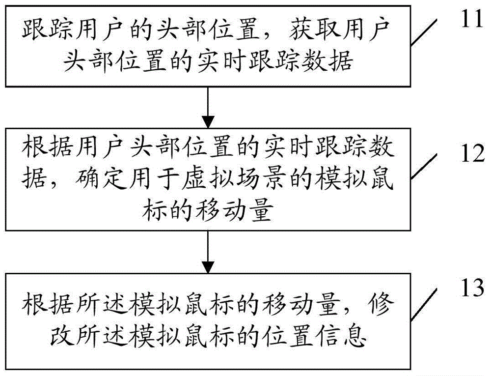
[0142] like Figure 5 As shown, the stereoscopic display method provided by Embodiment 4 of the present invention includes:

[0143] Step 41, track the user's head position, and acquire real-time tracking data of the user's head position.

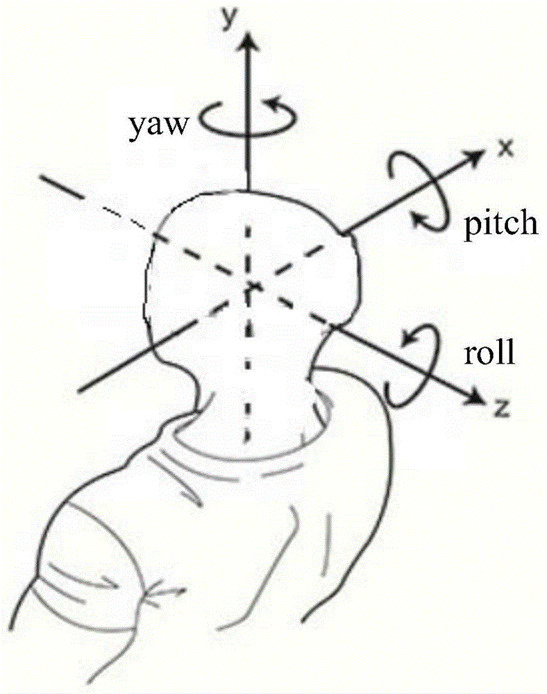
[0144] Specifically, such as figure 2 As shown, the real-time tracking data of the user's head is consistent with the real-time tracking data in Embodiment 1, and the description will not be repeated here. In the fourth embodiment, the observation matrix is ​​changed according to the real-time tracking data, so as to obtain a new observation matrix.

[0145] Step 42: When the position of the user's head changes, the original observation matrix of the virtual scene is transformed according to the real-time tracking data to obtain a new observation matrix.

[0146] In the fourth embodiment, the angle of view is deflected by changing the observation matrix, so as to realize the synchronization of the observation angles. Wherein, the origi...

specific Embodiment 5

[0187] like Image 6 As shown, Embodiment 5 of the present invention also provides a stereoscopic display method for virtual and real scenes, including:

[0188] Step 51, tracking the user's head position, and obtaining real-time tracking data of the user's head position;

[0189] Specifically, such as figure 2 As shown, the real-time tracking data of the user's head referred to in the fifth embodiment is consistent with the real-time tracking data of the user's head referred to in the first embodiment, and the description will not be repeated here.

[0190] Step 52, when the user's head position changes, transform the original projection matrix of the virtual scene according to the real-time tracking data to obtain a new projection matrix;

[0191] Wherein, the original projection matrix may also be called the current projection matrix, which refers to the projection matrix applied to the current stereoscopic image when the position of the user's head changes, that is, the...


PUM


Abstract

The invention provides a stereoscopic display method, a stereoscopic display device and stereoscopic display electronic equipment used for virtual and reality scenes. The stereoscopic display method comprises the steps of: acquiring real-time tracking data of a head position of a user; converting an original observation matrix or an original projection matrix of a virtual scene according to the real-time tracking data when the head position of the user changes, and acquiring a new observation matrix or a new projection matrix; and constructing and displaying a stereoscopic image of the virtual scene according to the new observation matrix or the new projection matrix, thereby converting an observation viewing angle of the virtual scene, and achieving synchronization of the observation viewing angle in the virtual scene and the observation viewing angle after the change of the head position of the user. The stereoscopic display method, the stereoscopic display device and the stereoscopic display electronic equipment can be applied to 3D display equipment.

Description

technical field [0001] The invention relates to the field of virtual reality technology, in particular to a stereoscopic display method, device and electronic equipment for virtual and real scenes. Background technique [0002] VR (Virtual Reality) refers to creating a realistic virtual reality effect through technical means. At present, virtual and reality equipment has gradually matured and improved, and has been widely used in fields such as film and television and games. More and more users have begun to choose virtual and reality equipment to experience 3D (3-dimensional, 3Dimensions) stereoscopic content. [0003] When users experience 3D stereoscopic content through virtual and real devices, in order to allow users to experience very realistic realistic effects, it is very important to synchronize the viewing angle of view, that is, when the user changes the position of the head to change the viewing angle of the eyes Therefore, the viewing orientation of the 3D cont...

Claims


Application Information

Patent Timeline
Patent Type & Authority Applications(China)
IPC IPC(8): H04N13/00H04N13/04H04N13/02
Inventor 刘江
Owner SUPERD CO LTD
Why Eureka
Try Eureka