a liquid reservoir

A liquid reservoir and vessel body technology, applied in the field of liquid reservoirs, can solve problems such as high coaxiality requirements, difficulty in welding and fixing, and fixation failure, so as to avoid coaxiality requirements, not easy to fatigue and loose, and good fixing effect Effect

Active Publication Date: 2018-05-01
ZHEJIANG SANHUA INTELLIGENT CONTROLS CO LTD
View PDF8 Cites 0 Cited by
  • Summary
  • Abstract
  • Description
  • Claims
  • Application Information

AI Technical Summary

Problems solved by technology

[0012] First, when assembling, if the upper end cover 1' assembly is combined with the fixed frame 6' first, and then assembled with the body 2', in order to ensure that the fixed frame 6' can smoothly enter the body 2', the surrounding wall of the fixed frame 6' There must be a gap between 6'2 and the inner wall of the body 2', which affects the fixing effect of the inlet pipe 4' and the outlet pipe 5';
[0013] If the upper end cover 1' assembly and the body 2' are welded and fixed first, and then the fixed plate 6'1 is assembled, the inlet through hole 6'1a and the outlet through hole 6'1b of the fixed plate 6'1 must be inserted into the inlet pipe 4 ’, the outlet pipe 5’, so that the coaxiality requirements for the inlet through hole 6’1a and the outlet through hole 6’1b of the fixed plate 6’1 and the inlet hole and the outlet hole of the upper end cover 1’ are relatively high, and the processing is difficult larger;
[0014] In addition, the inlet through hole 6'1a and the outlet through hole 6'1b should not be too large, so as not to have a large gap with the inlet pipe 4' and the outlet pipe 5', which will affect the fixing effect, and should not be too small, so as not to interfere with the upper end cover. The position deviation of the inlet and outlet holes of 1' makes it impossible to assemble, which also increases the processing difficulty of the fixing frame 6'
[0015] Second, the versatility of the fixed frame 6' is relatively poor, when the diameter of the liquid reservoir inlet pipe 4', the outlet pipe 5', or the diameter of the body 2', or the distance between the inlet hole and the outlet hole of the upper end cover 1' When there is a change, it is necessary to reset the matching fixing frame 6'
[0016] Third, because the fixed frame 6' is located inside the body 2', no matter which assembly method is adopted, it is not easy to be welded and fixed, so the fixed frame 6' can only be fixed by its outer wall and the inner wall of the body 2'. After operation, it is easy to cause fatigue loosening, resulting in fixed failure

Method used


Image

  • a liquid reservoir
  • a liquid reservoir
  • a liquid reservoir

Examples


Embodiment Construction

[0050] The core of the invention is to provide a liquid reservoir, which has a reliable structure, is easy to assemble, and has strong applicability.

[0051] In order to enable those skilled in the art to better understand the solution of the present invention, the present invention will be further described in detail below in conjunction with the accompanying drawings and specific embodiments.

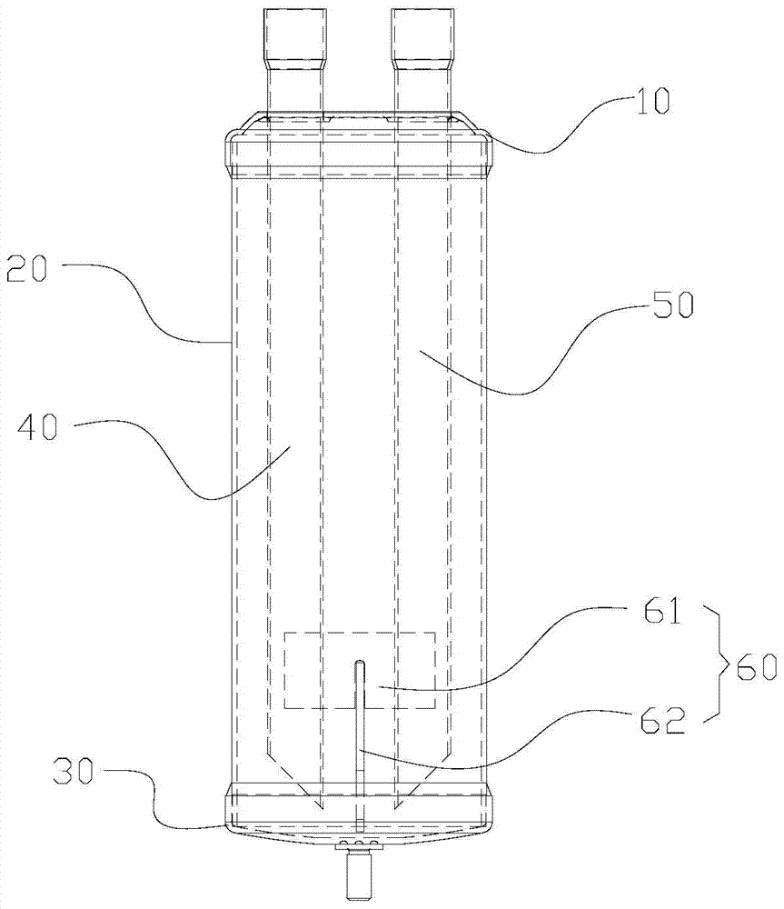
[0052] What needs to be explained here is that the orientation words "up" and "down" in this article are based on image 3 The components are located in the drawings and the positions of the components are defined only for the clarity and convenience of expressing the technical solution. It should be understood that the orientation words used herein shall not limit the scope of protection claimed by the application.

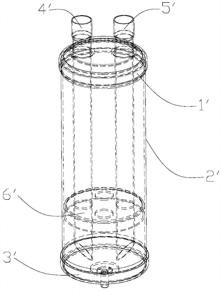
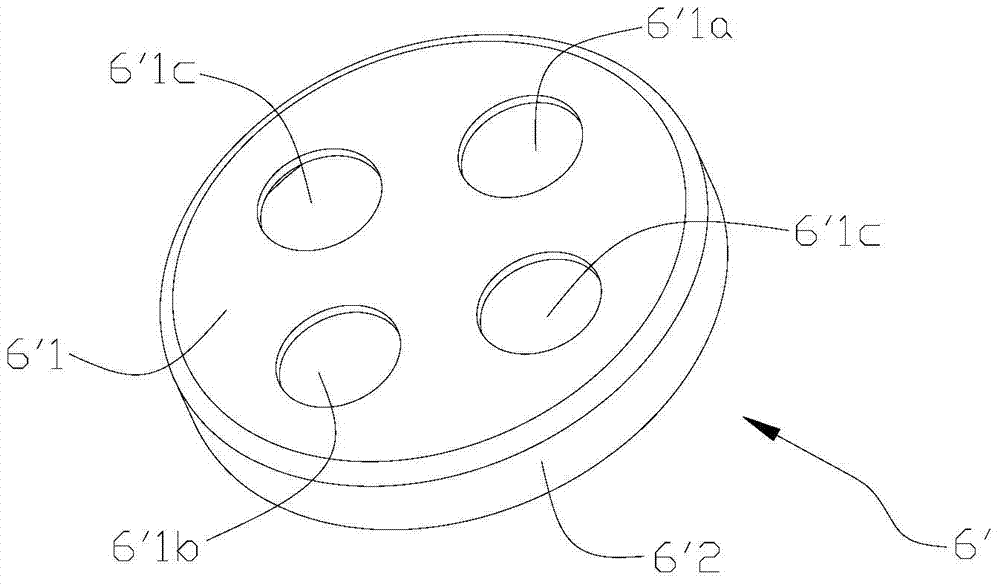
[0053] Please refer to image 3 , image 3 It is a structural schematic diagram of a specific embodiment of the liquid reservoir provided by the present invention. ...


PUM


Abstract

The invention discloses a liquid storage device which comprises a device body, a lower end cap firmly connected on the lower end of the device body as well as an inlet pipe and an outlet pipe stretching into the device body. The device also comprises a fixation frame, wherein the fixation frame specifically comprises a fixation plate and a flow blocking plate which are connected in a detachable manner; and the fixation plate is firmly connected to lower parts of the inlet pipe and the outlet pipe, and the flow blocking plate is firmly connected to the inner end face of the lower end cap. The liquid storage device has the advantages of easy assembly, a reliable structure and high applicability.

Description

technical field [0001] The invention relates to the technical field of refrigeration equipment, in particular to a liquid receiver. Background technique [0002] The liquid receiver is one of the important parts in the refrigeration system, usually installed after the condenser, and is located at the high pressure end of the system. The liquid receiver is mainly used to store high-pressure refrigerant to ensure that the refrigeration system needs to adjust the refrigerant storage volume when the cooling load changes. [0003] Please refer to figure 1 , figure 1 It is a structural schematic diagram of an existing liquid reservoir. [0004] As shown in the figure, the liquid receiver includes an upper end cover 1', a body 2' and a lower end cover 3', and the three are welded and fixed to form a cavity for containing refrigerant. [0005] Wherein, the upper end cover 1' has an inlet hole and an outlet hole, and the inlet pipe 4' and the outlet pipe 5' extend into the bottom...

Claims


Application Information

Patent Timeline
Patent Type & Authority Patents(China)
IPC IPC(8): F25B43/00
CPCF25B2400/16F25B43/00
Inventor 不公告发明人
Owner ZHEJIANG SANHUA INTELLIGENT CONTROLS CO LTD
Why Eureka
Try Eureka