Automatic roller shutter cup holder

A rolling shutter cup, automatic technology, applied in the special position of the vehicle, transportation and packaging, vehicle parts and other directions, can solve the problem of the sliding distance limitation of the rolling shutter, affecting the structural design of the automatic rolling shutter cup holder, etc. The effect of structural design freedom

Active Publication Date: 2016-07-13
NINGBO SHUAITELONG GRP CO LTD
View PDF6 Cites 0 Cited by
  • Summary
  • Abstract
  • Description
  • Claims
  • Application Information

AI Technical Summary

Problems solved by technology

[0002] The cup holder is a common accessory in the interior parts of the car. It plays a role in fixing its built-in during the driving process of the car. At present, there is an automatic roller shutter cup holder on the market. The two sides of the box body of the roller shutter cup holder A linear chute for the roller blind to slide is set on the top, and a motor is installed in the box body. A connecting rod fixedly connected to one end of the roller blind is installed on the output shaft of the motor, and the roller blind is driven to slide back and forth in the linear chute by driving the motor to rotate. The sliding distance of the roller blind cup holder is limited by the rotation angle of the connecting rod, and the drive motor needs to be set at the position where the axis is consistent with the rolling axis of the roller blind, which affects the structural design of the automatic roller shutter cup holder

Method used


Image

  • Automatic roller shutter cup holder
  • Automatic roller shutter cup holder
  • Automatic roller shutter cup holder

Examples


Embodiment Construction

[0019] Embodiments of the present invention will be further described below in conjunction with the accompanying drawings.

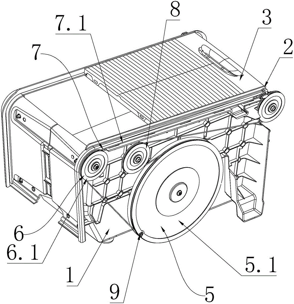
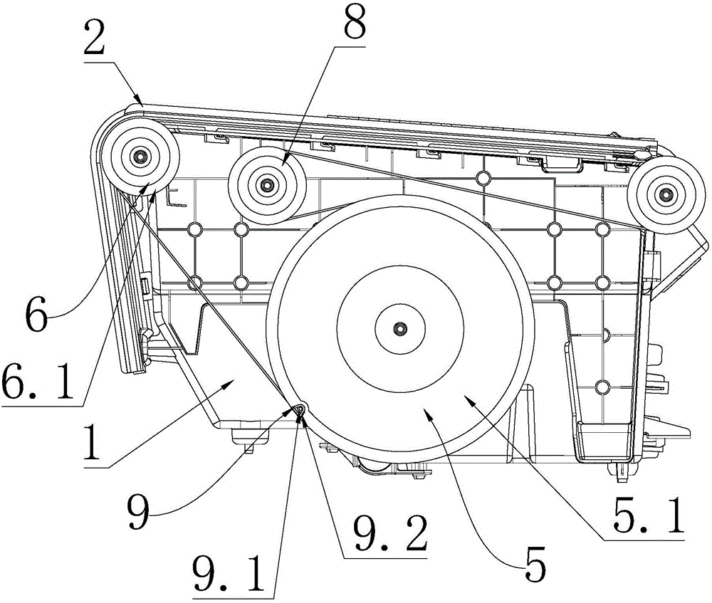
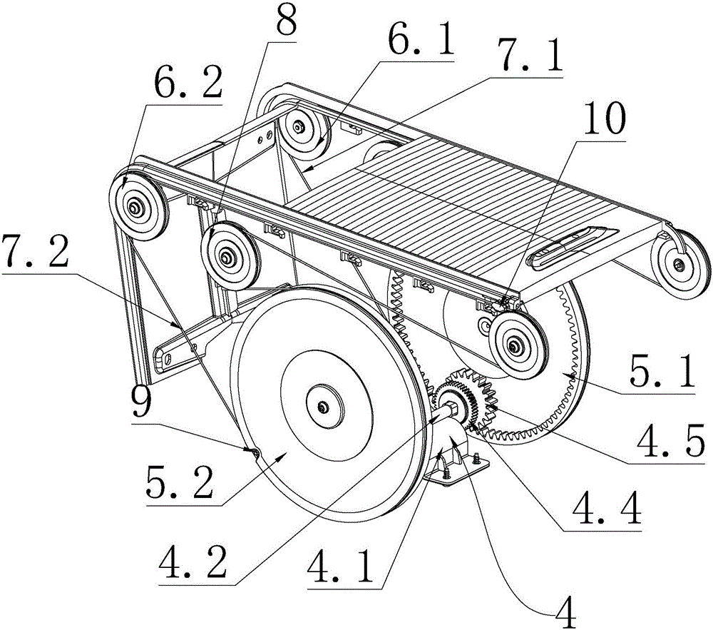
[0020] Such as Figure 1-5 as shown,

[0021] An automatic roller shutter cup holder, comprising a box body 1, a linear chute 2 arranged on both side walls of the box body 1 and a roller blind 3 matched with the two linear chutes 2, at least one side wall of the box body 1 There is a pulley mechanism for making the roller blind 3 slide back and forth along the linear chute 2, and the pulley mechanism includes a drive pulley 5 driven to rotate by the driving device 4, and is arranged at both ends of the linear chute 2 to make the roller blind 3 slide linearly. The guide pulley 6 and the sliding rope 7 that cooperates with the drive pulley 5 and the guide pulley 6 and is connected with the roller shade 3 to make the roller shade 3 slide back and forth.

[0022] Wherein, the pulley mechanism includes a first pulley mechanism arranged on one side of the bo...


PUM


Abstract

The invention discloses an automatic roller shutter cup holder which comprises a box body (1), linear sliding chutes (2) arranged on the two side walls of the box body (1) and a roller shutter (3) matched with the two linear sliding chutes (2), one or more side walls of the box body (1) are provided with pulley mechanisms which make the roller shutter (3) to slide back and forth along the linear sliding rails (2), and each pulley mechanism comprises a drive pulley (5) which is driven by a drive device (4) to rotate, guide pulleys (6) which are arranged at the two ends of the corresponding linear sliding chute (2) and used for making the roller shutter (3) conduct linear sliding and a sliding rope (7) which is matched with the drive pulley (5) and the guide pulleys (6) and connected with the roller shutter (3) to make the roller shutter (3) slide back and forth.By means of the automatic roller shutter cup holder, the sliding distance of the roller shutter and the arrangement position of a drive motor are not limited.

Description

technical field [0001] The invention relates to the technical field of automotive interior parts, in particular to an automatic roller shutter cup holder. Background technique [0002] The cup holder is a common accessory in the interior parts of the car. It plays a role in fixing the built-in parts of the car during the driving process. At present, there is an automatic roller shutter cup holder on the market. The two sides of the box body of the roller shutter cup holder A linear chute for the roller blind to slide is set on the top, and a motor is installed in the box body. A connecting rod fixedly connected to one end of the roller blind is installed on the output shaft of the motor, and the roller blind is driven to slide back and forth in the linear chute by driving the motor to rotate. The sliding distance of the roller blind cup holder is limited by the rotation angle of the connecting rod, and the drive motor needs to be set at a position where the axis is consisten...

Claims


Application Information

Patent Timeline
Patent Type & Authority Applications(China)
IPC IPC(8): B60N3/10
CPCB60N3/101
Inventor 吴志光吴俊男曹晓鹏田建开
Owner NINGBO SHUAITELONG GRP CO LTD
Why Eureka
Try Eureka