Disconnecting switch with counters

A technology of isolating switches and counters, applied in air switch parts, electrical components, etc., can solve problems such as difficult to estimate the aging degree of equipment, accidental closing, performance degradation, etc., achieve good application prospects and improve safety effects

Inactive Publication Date: 2016-07-13
JURONG HUAYUAN ELECTRICAL APPLIANCE EQUIP
View PDF6 Cites 4 Cited by
  • Summary
  • Abstract
  • Description
  • Claims
  • Application Information

AI Technical Summary

Problems solved by technology

[0002] During the manual operation of the isolating switch, due to differences in the habits, operation methods and strength of different operators, it is easy to cause accidental closing of the knife switch due to incomplete closing, resulting in false connection between the knife switch insurance and the contact point, or incomplete breaking. If the switch is not in place, although the circuit can be temporarily turned on, as the load increases, it is easy to cause overheating and burning of the dynamic and static contacts, and accidental switch-on may easily cause personal injury to the maintenance personnel.
At the same time, when the isolation switch is frequently operated, it is easy to cause equipment aging and performance degradation. The isolation switch is different from equipment such as transformers and circuit breakers, and has no characteristic quantities that directly reflect the status of its equipment. Inspection and operation inspection, lack of sufficient information and data support in equipment status evaluation and risk assessment, it is difficult to estimate the aging degree of equipment

Method used


Image

  • Disconnecting switch with counters

Examples


Embodiment Construction

[0013] The present invention will be further described below in conjunction with the accompanying drawings. The following examples are only used to illustrate the technical solution of the present invention more clearly, but not to limit the protection scope of the present invention.

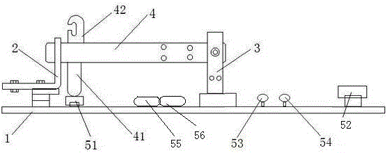
[0014] An isolating switch with a counter such as figure 1 As shown, it includes base 1, left gate 2, right gate 3, knife gate 4, knife gate status indicating device, first counter 55 and second counter 56, knife gate 4 and right gate 3 are hinged together, knife gate status indication The device comprises a first button 51, a second button 52 and a first indicator light 53 and a second indicator light 54 electrically connected to the two respectively, the first button 51 and the second button 52 are all fixed on the base 1, the first button 51 is arranged between the left gate 2 and the right gate 3, the second button is arranged on the right side of the right gate 3, the knife switch 4 is pro...


PUM


Abstract

The invention discloses a disconnecting switch with counters.The disconnecting switch comprises a base, a left gate, a right gate, a disconnecting link and a disconnecting link state indicating device; the disconnecting link and the right gate are hinged together; the disconnecting link state indicating device comprises a first button, a second button, a first indicator light and a second indicator light, wherein the first indicator light and the second indicator light are electrically connected with the first button and the second button respectively; the disconnecting link is provided with a left ejector rod and a second ejector rod.The disconnecting switch is characterized by further comprising the first counter and the second counter, and the first counter and the second counter are connected with the first button and the second button respectively and used for recording the number of in-place switch-on times and the number of thorough switch-off times of the disconnecting switch.The counters are arranged on the disconnecting switch to record the number of in-place switch-on times and the number of thorough switch-off times, and operation standardization of workers is supervised by comparing the two kinds of data, so that the safety of the disconnecting switch is improved, and the disconnecting switch has good application prospects.

Description

technical field [0001] The invention relates to an isolating switch with a counter, belonging to the technical field of power supply devices. Background technique [0002] During the manual operation of the isolating switch, due to differences in the habits, operation methods and strength of different operators, it is easy to cause accidental closing of the knife switch due to incomplete closing, resulting in false connection between the knife switch insurance and the contact point, or incomplete breaking. , Although the closing is not in place, although the circuit can be temporarily turned on, as the load increases, it is easy to cause overheating and burning of the dynamic and static contacts, and accidental closing is likely to cause personal injury to maintenance personnel. At the same time, when the isolation switch is frequently operated, it is easy to cause equipment aging and performance degradation. The isolation switch is different from equipment such as transform...

Claims


Application Information

Patent Timeline
Patent Type & Authority Applications(China)
IPC IPC(8): H01H31/02H01H21/54
CPCH01H31/02H01H21/54
Inventor 汤茜汤永春
Owner JURONG HUAYUAN ELECTRICAL APPLIANCE EQUIP
Why Eureka
Try Eureka