
Device and method for handling, mounting or demounting components of wind turbine

A technology of wind power generation equipment and components, which is applied in the field of rotor blades and/or nacelle devices, and can solve problems such as difficult rotor blade adjustment assembly positions, invisible assembly states, etc.

Inactive Publication Date: 2016-07-13
MAX BOGL WIND
View PDF2 Cites 2 Cited by
  • Summary
  • Abstract
  • Description
  • Claims
  • Application Information

AI Technical Summary

Problems solved by technology

Here, it is difficult to adjust the rotor blade to the desired assembly position, because the person holding the cable on the ground cannot see the assembly state on the hub from above

Method used


Image

  • Device and method for handling, mounting or demounting components of wind turbine
  • Device and method for handling, mounting or demounting components of wind turbine
  • Device and method for handling, mounting or demounting components of wind turbine

Examples


Embodiment Construction

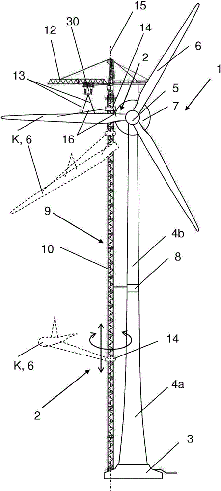
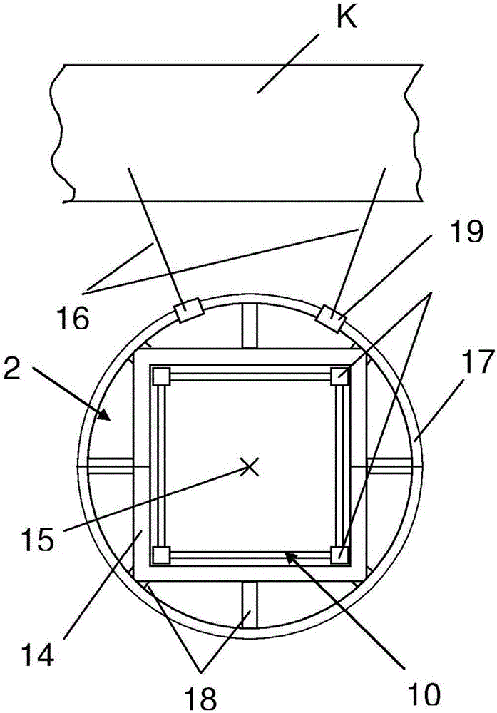
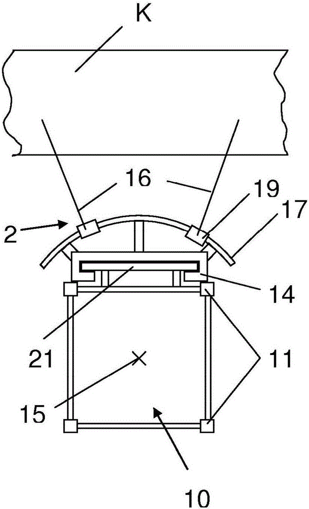
[0031] figure 1 The device and method for operating, assembling or disassembling components of a wind power plant and a wind power plant 1 under construction are shown in a schematic overview. Here, the wind power plant 1 consists of a base 3, a tower 4 and different functional units (of which a hub 5 with rotor blades 6 and a nacelle 7 can now be seen) in a known manner. According to this figure, the tower body 4 is here divided into two segments 4 a, 4 b, which are connected to each other by an intermediate piece 8. In principle, the tower body 4 can be composed of cast-in-place concrete, prefabricated concrete or steel, or be built with a mixed structure of different materials. Preferably, the lower section 4a of the tower body is composed of a concrete prefabricated part, which supports each other between the middle part 8 and the base 3, and the steel as the second section 4b is supported on the lower section. For the mast, the second section can be one piece or can also ...


PUM


Abstract

A device (2) for handling, mounting or demounting components (K, 5, 6, 7) of a wind turbine (1), in particular rotor blades (6) and / or a nacelle (7), with the aid of a crane (9) comprises a support (14) which can be connected to the crane (9) while being movable in the direction of a longitudinal axis (15) of said crane, and at least one guying device (16), preferably a guy cable (16a), which is connected at its first end to the movable support (14) and which can be connected by its second end to the component (K, 5, 6, 7) of the wind turbine (1) in order to stabilze the position of the component (K, 5, 6, 7) during handling and mounting. The guying device (16) is connected to the support (14) while being rotatable about the longitudinal axis (15) of the crane (9), preferably being rotatable through at least 90 degrees, more preferably being rotatable through at least 360 degrees, particularly preferably being rotatable through at least 380 degrees. In a method for handling, mounting or demounting components (K, 5, 6, 7) of a wind turbine (1), in particular rotor blades (6) and / or a nacelle (7), with the aid of a crane (9), the position of the component (K, 5, 6, 7) during handling and mounting or demounting is stabilized by means of at least one guying device (16), and the at least one guying device (16) is moved in the direction of a longitudinal axis (15) of the crane (9) during a vertical lifting movement of the component (K, 5, 6, 7). Before and / or during and / or after a vertical lifting movement of the component (K, 5, 6, 7), the at least one guying device (16) is rotated about the longitudinal axis (15) of the crane (9).

Description

Technical field [0001] The invention relates to a device for operating, assembling or disassembling components of a wind power plant, in particular rotor blades and / or nacelles, by means of a crane. The device includes a movable bracket that is movably connected to the crane in the direction of the longitudinal axis of the crane. The device also includes at least one tensioning device, preferably a cable, which is connected to a movable support at its first end, and can be connected to a component of the wind power plant at its second end, so as to The position of stable components during operation and assembly. The invention also relates to a corresponding method in which the position of the member to be lifted is stabilized by means of at least one tensioning device during operation and assembly or disassembly. In this case, the at least one tensioning device is moved in the direction of the longitudinal axis of the crane during the vertical lifting movement of the component...

Claims


Application Information

Patent Timeline
Patent Type & Authority Applications(China)
IPC IPC(8): B66C23/18F03D1/00
CPCB66C23/185F03D13/10F05B2230/61F05B2230/70Y02E10/72Y02E10/74Y02P70/50B66C23/207F03D1/0675F03D3/064
Inventor 斯特凡·博格尔约翰·怀尔德
Owner MAX BOGL WIND
Learn More