
Color coding ring for spray guns

A technology of spray guns and color codes, which is applied in the direction of spraying devices, liquid spraying devices, single handheld devices, etc., to achieve the effect of simple identification

Inactive Publication Date: 2016-07-27
3M INNOVATIVE PROPERTIES CO
View PDF6 Cites 1 Cited by
  • Summary
  • Abstract
  • Description
  • Claims
  • Application Information

AI Technical Summary

Problems solved by technology

Also, more than one painter may be working in the same area

Method used


Image

  • Color coding ring for spray guns
  • Color coding ring for spray guns
  • Color coding ring for spray guns

Examples


Embodiment Construction

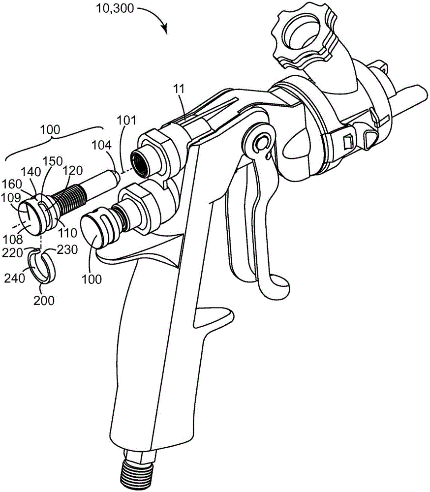
[0039] see now figure 1 , shows an exemplary spray gun 10 according to the present disclosure. While the spray gun 10 shown is a gravity-feed spray gun 10 featuring a removable spray nozzle assembly, the present disclosure is applicable to any spray gun 10 having one or more rotatable control knobs, including, for example, gravity-feed spray guns, siphon Feed guns, HVLP guns, compatible guns, airless and air assisted guns. Additionally, spray guns according to the present disclosure may be used to spray or apply (ie, as in applying non-atomized beads) any fluid, such as paint, stain, adhesive, sealant, or other coating.

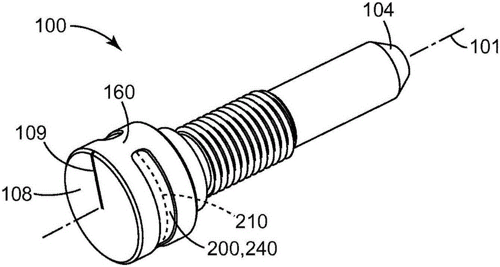
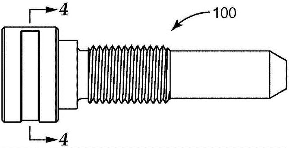
[0040] Spray gun 10 includes one or more rotatable control knobs for adjusting settings on spray gun 10 . For example, rotatable control knob 100 may be used to adjust a valve to regulate the flow of air (or other gas) or fluid through spray gun 10 . Rotatable control knob 100 may also be used to adjust the travel of the trigger on spray gun 10 . Typicall...


PUM


Abstract

A spray gun (10) comprising a rotatable control knob (100) is disclosed. The rotatable control knob (100) comprises a gripping surface (110) at least partially surrounding a rotation axis (101), an attachment end (104) disposed along the rotation axis (101) for rotatable connection of the control knob (100) to the spray gun (10), an indicator retaining feature (120) on the gripping surface extending in a retaining feature trajectory about the rotation axis from a first retainer end (140) to a second retainer end (150), and a gripping surface position indicator (200) separating the first retainer end from the second retainer end. The gripping surface position indicator indicates the rotational position of the control knob about the rotation axis. Also disclosed are indicators to be retained by the indicator retaining feature.

Description

Background technique [0001] Spray guns are often used to apply paint in many fields. In some fields, such as vehicle collision repair, painters may use multiple spray guns for different jobs, or even for a single job. For example, a painter may need to apply a primer coat, a base coat, and a clear coat to complete a single restoration. These different steps may require spray guns with, for example, different sized orifices to accommodate paints of different viscosities. Additionally, more than one painter may be working in the same area. There is a need to provide identification of spray guns to identify their intended use and / or user. Contents of the invention [0002] Exemplary embodiments according to the present disclosure include, but are not limited to, the following embodiments, which may or may not be numbered for convenience. Several additional embodiments, not specifically enumerated in this section, are disclosed in the accompanying Detailed Description. [0...

Claims


Application Information

Patent Timeline
Patent Type & Authority Applications(China)
IPC IPC(8): B05B7/02B05B9/01B05B11/00
CPCB05B7/02B05B7/12B05B9/01G09F3/02
Inventor 布赖恩·E·邓肯埃里克·O·纳亚里博小约翰·I·埃斯科托
Owner 3M INNOVATIVE PROPERTIES CO
Learn More