Adjustable self-adaptive wire spool device

A winding reel, self-adaptive technology, applied in the field of adjustable self-adaptive winding reel device, can solve the problems of speed mismatch, increase of winding reel speed, increase of winding reel speed, etc., and achieve self-adaptive external force interference , increase friction, overcome the effect of external force

Inactive Publication Date: 2016-08-03
CHONGQING CITY SOUTH FLAME RETARDANT WIRE & CABLE CO LTD
View PDF6 Cites 1 Cited by
  • Summary
  • Abstract
  • Description
  • Claims
  • Application Information

AI Technical Summary

Problems solved by technology

Although the existing winding reel can meet the requirements of use to a certain extent, in the process of use, there is often a problem that the rotating speed of the winding reel does not match the speed of winding or paying off the wire. For example, when winding the wire, suddenly Applying a large torque to the winding reel will cause the speed of the winding reel to increase suddenly, which will cause its speed to exceed the speed required for winding the wire, and then apply a large traction force to the wire, which exceeds the speed of the wire. If it is within the bearing range, the quality of the wire will be damaged or even disconnected; if a large instantaneous pulling force is applied to the wire when paying off the wire, the speed of the driving reel will suddenly increase, which exceeds the limit of the wire. The required speed, so that the excess wire will be piled up on the ground, which is not conducive to safe production; and in the process of unwinding, it is often necessary to apply a pre-added traction to the wire, and the existing winding reel cannot meet the requirements. Line exerted traction requirements

Method used


Image

  • Adjustable self-adaptive wire spool device
  • Adjustable self-adaptive wire spool device
  • Adjustable self-adaptive wire spool device

Examples


Embodiment Construction

[0024] The present invention will be further described below in conjunction with the accompanying drawings and specific embodiments, so that those skilled in the art can better understand the present invention and implement it, but the examples given are not intended to limit the present invention.

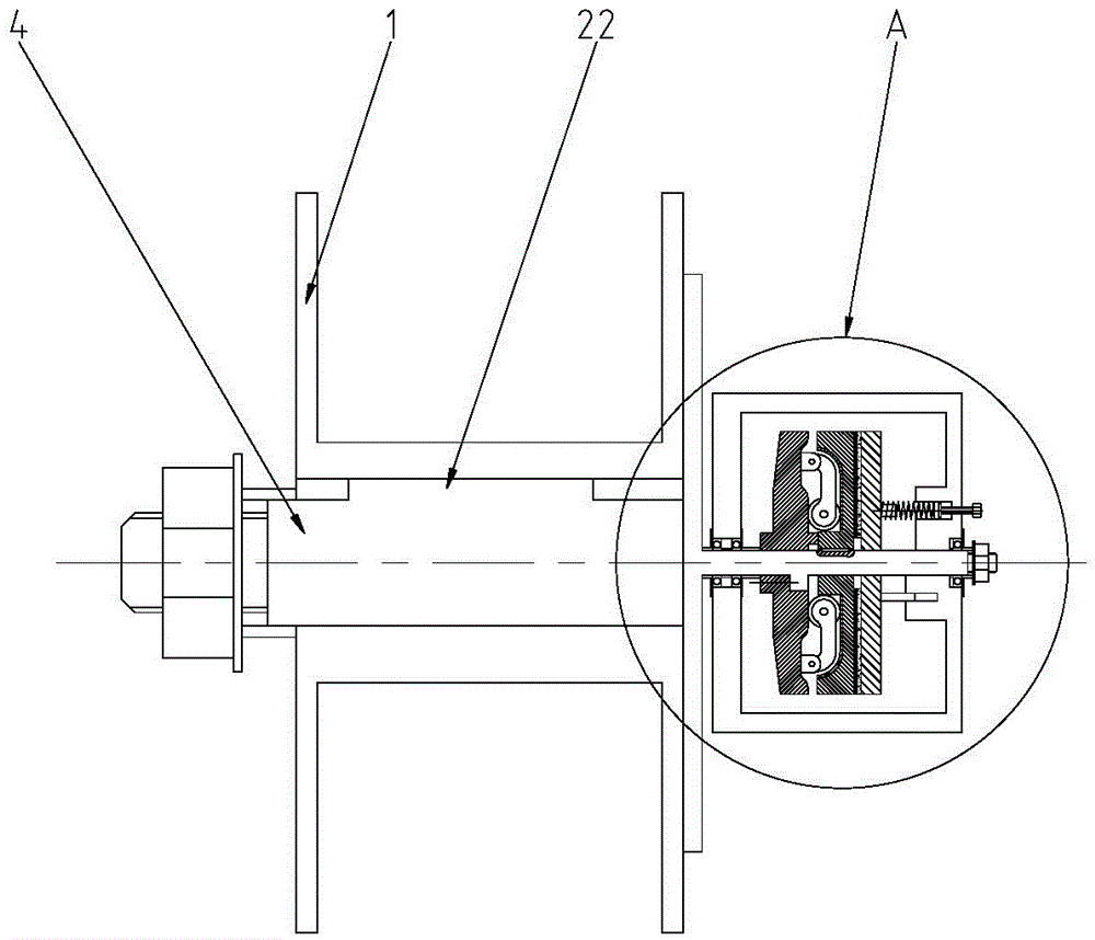
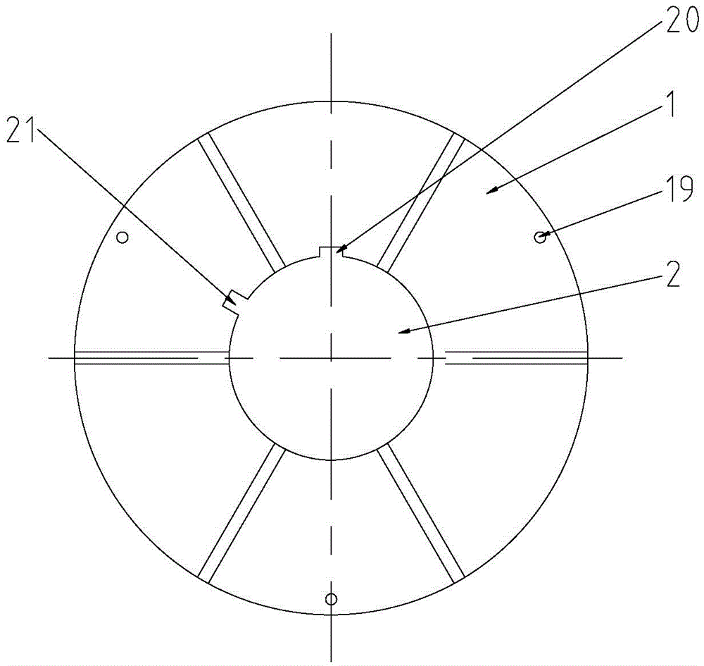
[0025] Such as figure 1 As shown, it is a schematic structural diagram of an embodiment of the adjustable self-adaptive winding reel device of the present invention. The adjustable self-adaptive reel device of this embodiment includes a reel body 1, a central through hole 2 is provided in the middle of the reel body 1, and a hole for winding is provided on the outer peripheral wall of the reel body 1. The winding groove 3 and the central through hole of the winding reel body 1 are fitted with a rotating shaft 4 which rotates synchronously with it, and an adaptive friction mechanism is installed on the rotating shaft 4 .

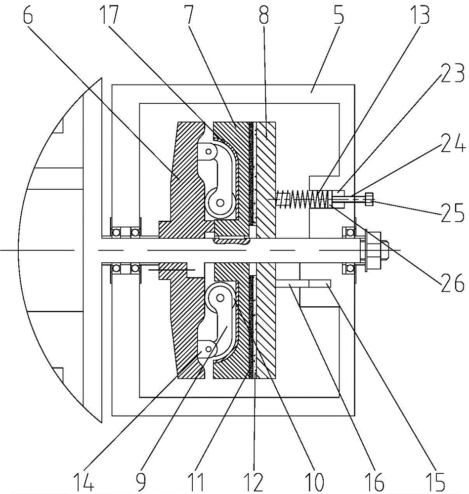
[0026] The self-adaptive friction mechanism of this embodi...


PUM


Abstract

An adjustable self-adaptive winding reel device, comprising a winding reel body, the winding reel body is provided with a central through hole, and the outer peripheral wall of the winding reel body is provided with a winding groove, the center of the winding reel body is through A rotating shaft is set in the hole, and an adaptive friction mechanism is installed on the rotating shaft; the adaptive friction mechanism includes a housing, and the rotating arm disc, friction disc I and friction disc II are arranged in the housing; the friction disc I is located on the rotating arm disc Between the friction disk II and the friction disk I, a rotating arm mechanism is provided on the side of the rotating arm disk facing the friction disk I. The rotating arm mechanism includes a rotating arm located in the radial direction of the rotating arm disk, and one end of the rotating arm is hinged to the rotating arm disk. Connected, and the other end of the rotating arm is provided with a roller; there is a friction surface that cooperates with each other between the friction disc Ⅰ and the friction disc Ⅱ; a spring and a sliding guide mechanism are provided between the friction disc Ⅱ and the housing; Groove, and the bottom of the groove is provided with an adjustment mechanism for adjusting the pre-pressure exerted by the spring on the friction disc II.

Description

technical field [0001] The invention relates to a cable winding device, in particular to an adjustable self-adaptive winding reel device. Background technique [0002] The existing winding reels generally include a winding reel main body, a central through hole is set in the middle of the winding reel main body, and a winding groove is arranged on the outer peripheral wall of the winding reel main body. The reel can realize the purpose of winding or paying off the wire. Of course, when paying out the wire, the pulling wire can also be directly used to drive the winding reel to rotate to realize the purpose of paying out the wire. Although the existing winding reel can meet the requirements of use to a certain extent, in the process of use, there is often a problem that the rotating speed of the winding reel does not match the speed of winding or paying off the wire. For example, when winding the wire, suddenly Applying a large torque to the winding reel will cause the speed...

Claims


Application Information

Patent Timeline
Patent Type & Authority Applications(China)
IPC IPC(8): B65H75/34B65H75/44
CPCB65H75/34B65H75/4442
Inventor 杨炳生
Owner CHONGQING CITY SOUTH FLAME RETARDANT WIRE & CABLE CO LTD
Why Eureka
Try Eureka