A terminal block

A technology of terminal block and shrapnel, applied in the direction of contact parts, clamping/spring connection, etc., can solve the problems of terminal losing wiring function, easy to fall off and damage, etc., and achieve the effect of optimizing structure size and reducing structure width

Active Publication Date: 2019-02-05
NINGBO SUPU ELECTRONICS
View PDF6 Cites 1 Cited by
  • Summary
  • Abstract
  • Description
  • Claims
  • Application Information

AI Technical Summary

Problems solved by technology

The shrapnel is easy to fall off and damage during the repeated insertion process, so that the terminal block loses its wiring function.

Method used


Image

  • A terminal block
  • A terminal block
  • A terminal block

Examples


Embodiment 1

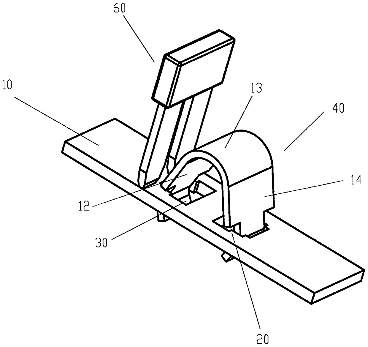
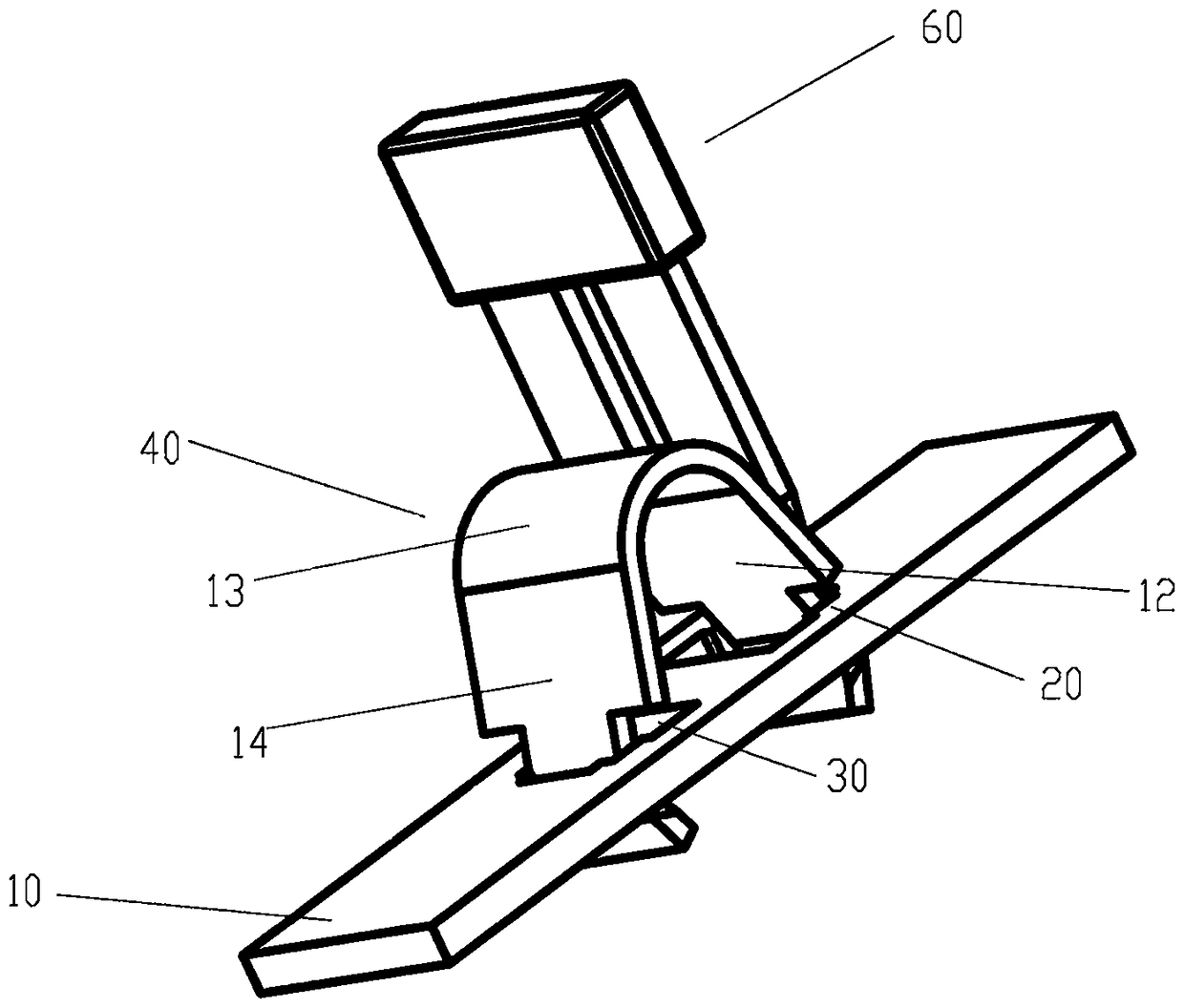
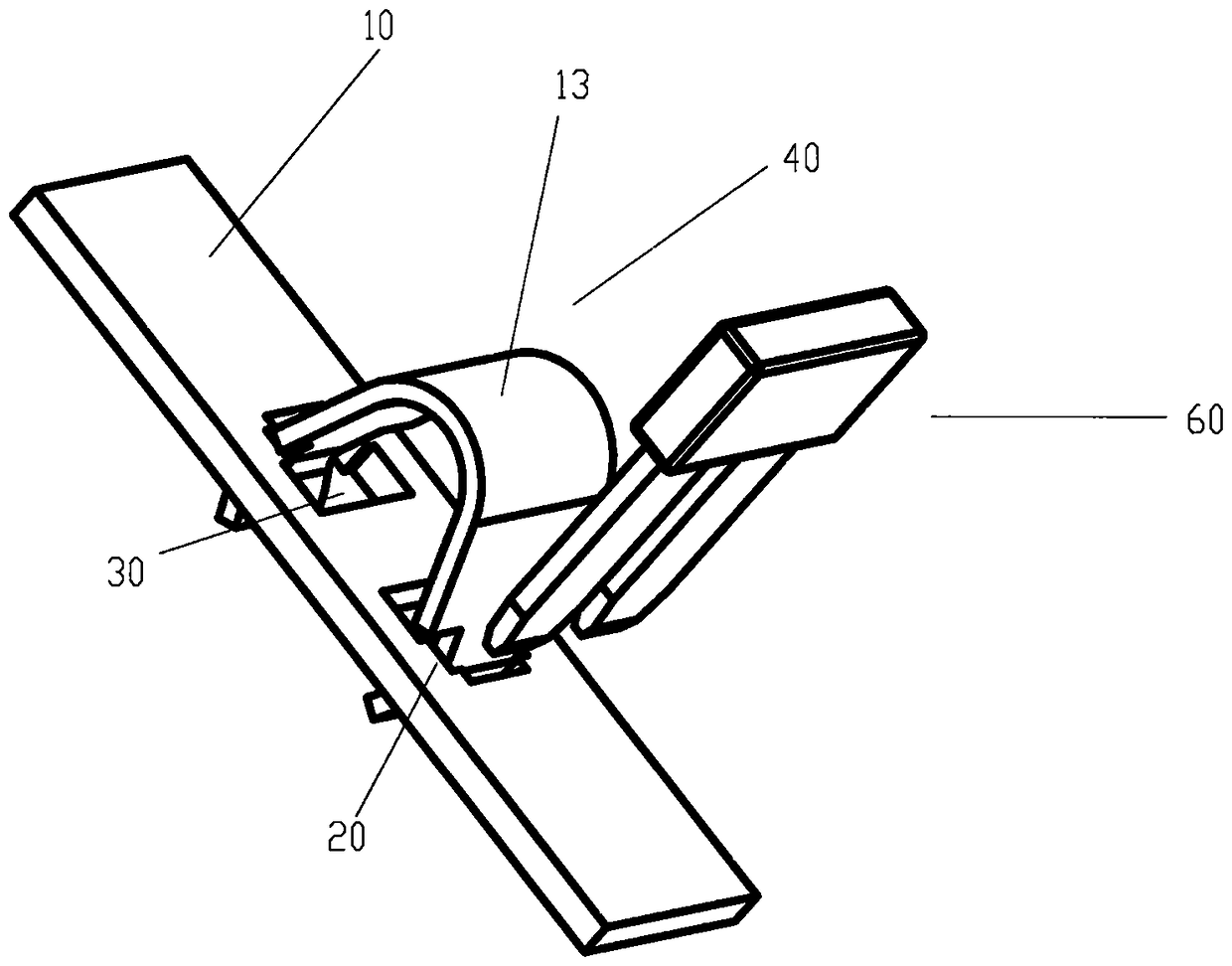
[0025] Such as Figure 1-4 As shown, the present invention provides a terminal block. The main body structure 10 of the metal plate of the terminal block is roughly a rectangular hexahedron, and at least one groove portion 30 is arranged on it. Preferably, the groove portion 30 penetrates through the main body of the metal plate. Through hole of structure 10 . Moreover, the corner of at least one side wall 20 of the groove portion 30 is formed in a stepped shape.

[0026] The terminal block also has an elastic piece 40, the elastic piece has an obvious U-shaped bending portion 13, and the bending portion 13 has an obvious bending radius, and when it is in a rest position, it can make the first arm portion 12 and the second arm portion 12 of the elastic piece The two arm parts 14 have at least elasticity to be far away from each other.

[0027] Preferably, near the middle of the metal plate main structure 10, two mirror-symmetric grooves 30 are arranged along the longitudinal...

Embodiment 2

[0033] Unlike the elastic piece in Embodiment 1, which has an obvious bending radius, the bending portion 13 of the elastic piece is in the extension of the first arm portion 12 and the second arm portion 14, gradually making the first arm portion 12 and the second arm portion 14 The ends of the two arm parts 14 abut against each other, so that the structural width of the elastic piece in the clamping direction can be reduced, thereby optimizing the structural size of the entire terminal.

[0034] Preferably, the ends of the first arm portion 12 and the second arm portion 14 of the elastic piece 40 are folded and abutted together at the bending portion 13, such folded abutment passes through making the first arm portion 12 and the second arm portion 14 of the elastic piece 40 The arm portion 14 is bent by 180°, and the preferred elastic sheet is made of high-quality spring steel sheet, which is folded during the deformation process.

[0035] Optionally, the first arm 12 and th...


PUM


Abstract

The invention discloses a binding post strip. The binding post strip is provided with a metal plate main structure (10) and an elastic sheet (40), wherein the metal plate main structure (10) is a rectangular hexahedron, and is provided with at least one groove unit (30), thus being convenient for connection with the elastic sheet (40) elastically; and elasticity for mutually at least separating a first arm portion (12) of the elastic sheet (40) from a second arm portion (14) of the elastic sheet (40) exists between the first arm portion (12) and the second arm portion (14) of the elastic sheet (40). The binding post strip is characterized in that: the corner, of a side wall (20) which touches the first arm portion (12) and the second arm portion (14) of the elastic sheet, in the groove unit (30) forms a mutually symmetrical iterated ladder shape; and the elastic sheet (40) can be plugged in the groove unit in an assembled way, and two sides of the elastic sheet are clamped in the groove unit to prevent from falling off.

Description

technical field [0001] The invention relates to a connection component for electrical equipment, in particular to a terminal block. Background technique [0002] It is widely required to use jumper or bridging devices in electrical equipment, or to contact electrical conductors. A typical terminal for contacting flexible electrical conductors is a screw terminal. A traditional screw terminal includes a screw for clamping a flexible electrical wire, which can be rotated to connect to the corresponding screw hole, and the flexible electrical wire to be connected is clamped between the head of the screw and the connecting part , so that the flexible electrical conductor and the contact point are clamped and contacted. In order to prevent the ends of flexible electrical conductor strands (often using thin copper wires) from loosening, and to ensure good contact between the wires and the intended contact point, the ends are generally terminated with metal conductive attachments...

Claims


Application Information

Patent Timeline
Patent Type & Authority Patents(China)
IPC IPC(8): H01R13/02H01R4/48
CPCH01R4/48H01R13/02
Inventor 卢迪马晓轩
Owner NINGBO SUPU ELECTRONICS
Why Eureka
Try Eureka