Supercharge Your Innovation With Domain-Expert AI Agents!

Connecting node plate with sliding end plate for buckling-restrained brace

一种防屈曲支撑、连接节点的技术,应用在防震、建筑维修、建筑构件等方向,能够解决刚域效应、节点板开合效应、梁柱计算长度缩短等问题,达到延长使用寿命、避免刚域效应的效果

Active Publication Date: 2016-08-10
SOUTH CHINA UNIV OF TECH +2
View PDF8 Cites 17 Cited by
  • Summary
  • Abstract
  • Description
  • Claims
  • Application Information

AI Technical Summary

Problems solved by technology

[0010] The object of the present invention is to provide a connecting gusset plate with slip end plate for anti-buckling support, so as to solve the rigid domain effect caused by the weld connection of the connecting gusset plate in the prior art, and the calculation length of the beam and column is shortened And the opening and closing effect of the structure on the gusset plate

Method used


Image

  • Connecting node plate with sliding end plate for buckling-restrained brace
  • Connecting node plate with sliding end plate for buckling-restrained brace
  • Connecting node plate with sliding end plate for buckling-restrained brace

Examples


Embodiment 1

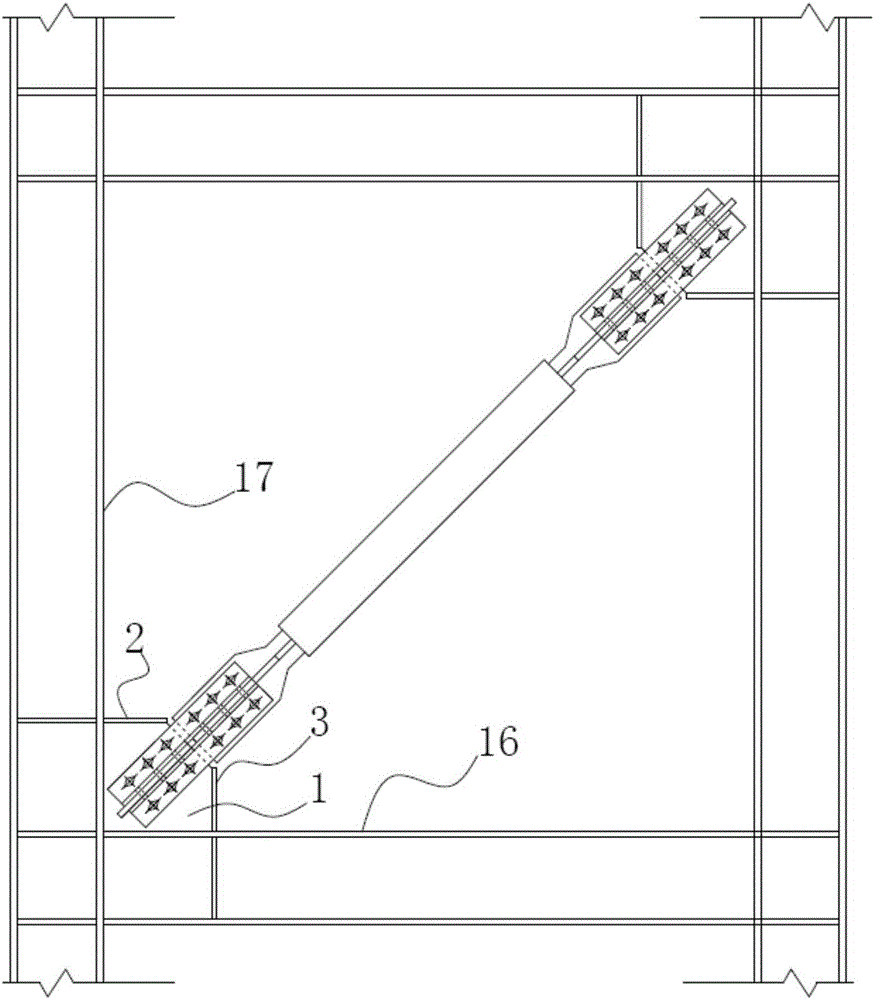
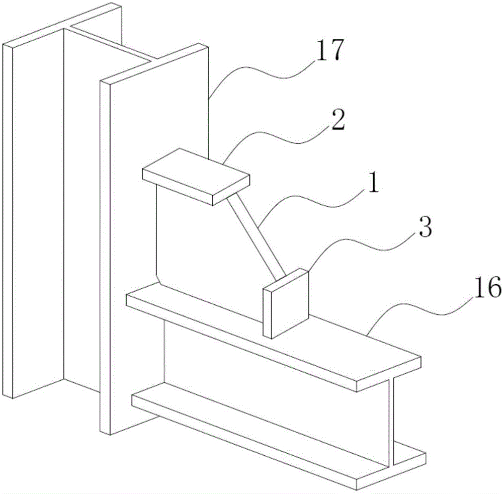
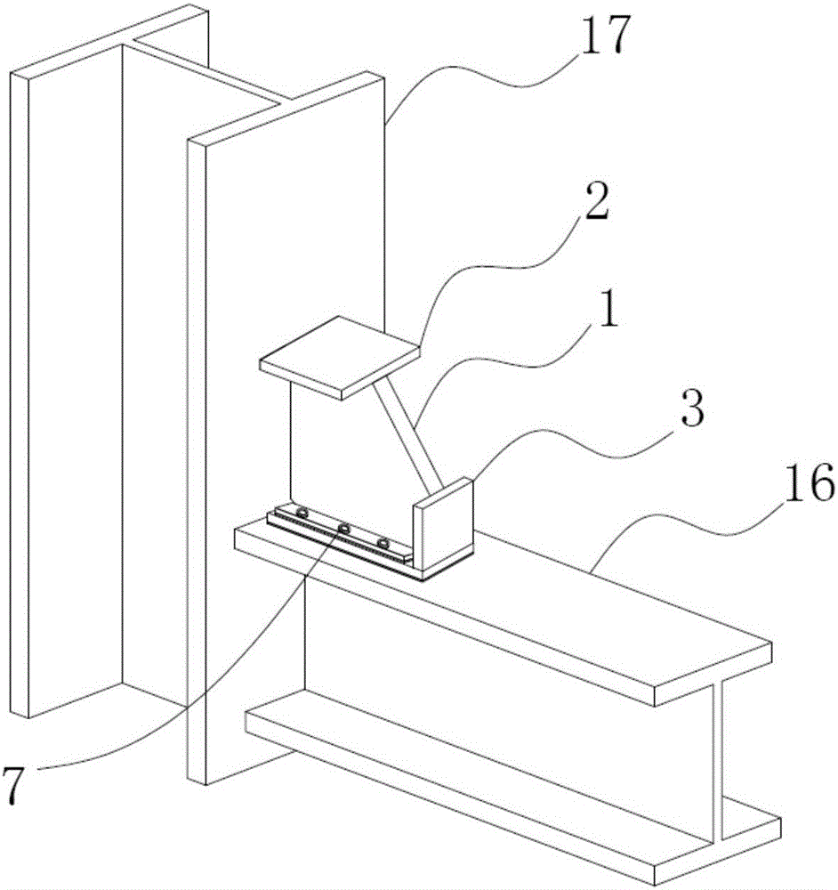
[0040] This embodiment provides a connecting gusset plate with slip end plates for buckling-resistant bracing, wherein: figure 1 It is the structural diagram of the overall connection between buckling-resistant braces and beams and columns; image 3 Schematic diagram of the structure of the connecting gusset plate with sliding end plate for anti-buckling support provided by Embodiment 1 of the present invention, Figure 4 An exploded view of the connecting gusset plate with sliding end plates for anti-buckling braces provided by Embodiment 1 of the present invention. Such as figure 1 , 3 , 4, the main structure of the connecting gusset plate with slip end plate used for buckling-resistant support includes a central plate 1, a first rib plate 2, a second rib plate 3, a horizontal end plate 4, and a first horizontal backing plate 5 , the second horizontal backing plate 6, the bolt 7 and the non-adhesive layer 8. Specifically, the horizontal end plate 4 is perpendicular to th...

Embodiment 2

[0046] The connecting gusset plate with sliding end plates in this embodiment is further provided with a vertical end plate 11 , a first vertical backing plate 12 , and a second vertical backing plate 13 . Figure 5 Schematic diagram of the structure of the connecting gusset plate with slip end plate for anti-buckling support provided by Embodiment 2 of the present invention; Figure 6 An exploded view of the connecting gusset plate with sliding end plates for anti-buckling braces provided by Embodiment 2 of the present invention. Such as Figure 5 , 6 As shown, specifically, the vertical end plate 11 is perpendicular to the central plate 1 and the horizontal end plate 4 respectively, and is fixedly arranged on the left end surface of the central plate 1 corresponding to the second rib 3 . The first vertical backing plate 12 and the second vertical backing plate 13 are both arranged on the right surface of the vertical end plate 11 and located on two sides of the central pla...


PUM


Abstract

The invention provides a connecting node plate with a sliding end plate for a buckling-restrained brace. The connecting node plate comprises a center plate, a first rib plate, a second rib plate, a horizontal end plate, a first horizontal cushion plate, a second horizontal cushion plate, bolts and non-adhering layers, wherein the horizontal end plate is vertical to the center plate, and is fixedly arranged at the lower end surface of the center plate; the first horizontal cushion plate and the second horizontal cushion plate are respectively arranged at the upper surface of the horizontal end plate, and are respectively positioned at the two sides of the center plate; first through holes are formed in the horizontal end plate, first mounting holes are formed in the first horizontal cushion plate and the second horizontal cushion plate, and the non-adhering layers are respectively arranged at the bottom surface of the horizontal end plate, between the horizontal end plate and the first horizontal cushion plate, and between the horizontal end plate and the second horizontal cushion plate. The connecting node plate has the advantages that the adverse influence of beam column opening and closing effect to the node plate is decreased, the influence of the node plate to the beam column rigid area effect and computing length is decreased, the stress distribution of the node plate is more uniform, and the design and construction are simpler and more convenient.

Description

technical field [0001] The invention relates to the technical field of civil engineering structures, in particular to a connecting gusset plate with a sliding end plate used for anti-buckling supports. Background technique [0002] Anti-buckling bracing is currently being used as a new energy-dissipating and shock-absorbing component in civil building structures, especially in multi-story buildings. dissipate seismic energy. In practical applications, buckling-resistant braces must be connected to beams and columns through gusset plates. figure 1 It is the structural diagram of the overall connection between buckling-resistant braces and beams and columns, figure 2 A schematic diagram of the connection gusset plate structure for traditional buckling-resistant braces, such as figure 1 , 2 As shown, the traditional connection method is to connect the gusset plate with the flange of the steel column and steel beam through fillet welds, and the buckling-resistant brace conn...

Claims


Application Information

Patent Timeline
Patent Type & Authority Applications(China)
IPC IPC(8): E04H9/02E04B1/98
CPCE04H9/0237E04H9/027E04B2001/2496E04B1/2403E04B1/5812E04B2001/2415E04B2001/2448E04B2001/2457E04H9/024E04G23/0218E04B1/98
Inventor 赵俊贤陈若冰马容全苗冬梅范新海白佳楠韩伟周璋鑫郑棉灿黄英翔王丹杨林黄庆
Owner SOUTH CHINA UNIV OF TECH
Features
  • R&D
  • Intellectual Property
  • Life Sciences
  • Materials
  • Tech Scout
  • Unparalleled Data Quality
  • Higher Quality Content
  • 60% Fewer Hallucinations
Learn More