
Steel structure node connecting structure for building and connecting method thereof

A node connection and steel structure technology, which is applied to building components, building structures, buildings, etc., can solve the problems of internal stress, use safety threats, and lack of adjustment ability in the node connection structure, so as to achieve a stable and reliable connection structure. Small impact, improved shock resistance and stability

Active Publication Date: 2020-03-17
TANGSHAN SINOMA HEAVY MASCH CO LTD
View PDF7 Cites 4 Cited by
  • Summary
  • Abstract
  • Description
  • Claims
  • Application Information

AI Technical Summary

Problems solved by technology

Especially when building a complex space steel structure system, due to the limitations of the specific structure, for example, the space steel structure is an irregular multi-dimensional structure, and the connection of the components at the nodes is not a horizontal and vertical "cross" connection, and there are also grounds in actual installation. There is a need to adjust the connection angle under working conditions, but the existing node structures are mostly "ten"-shaped connections or fixed angle connections, which do not have the ability to adjust, and forced installation will also cause internal stress in the node connection structure, which poses a threat to the safety of use

Method used


Image

  • Steel structure node connecting structure for building and connecting method thereof
  • Steel structure node connecting structure for building and connecting method thereof
  • Steel structure node connecting structure for building and connecting method thereof

Examples


Embodiment Construction

[0023] The present invention will be further described below in conjunction with accompanying drawing:

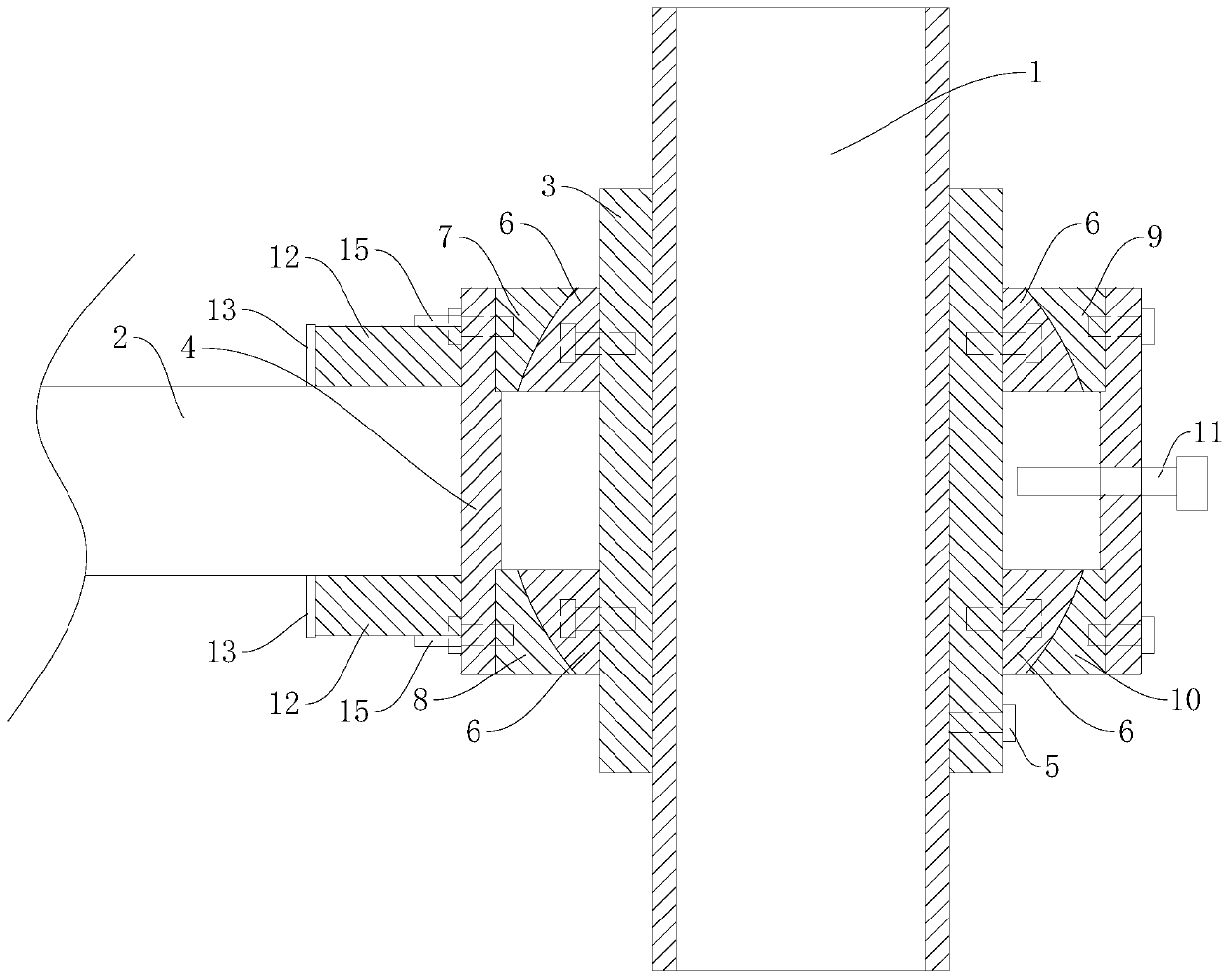
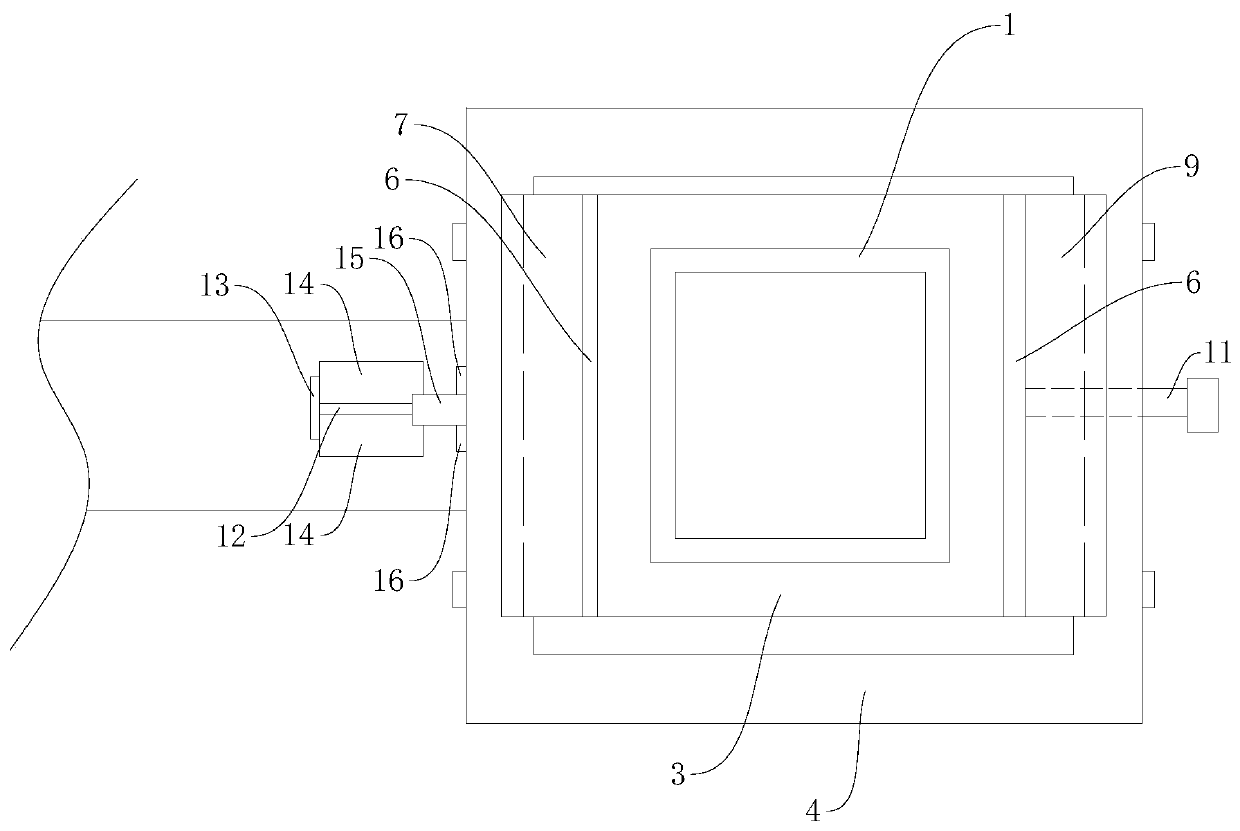
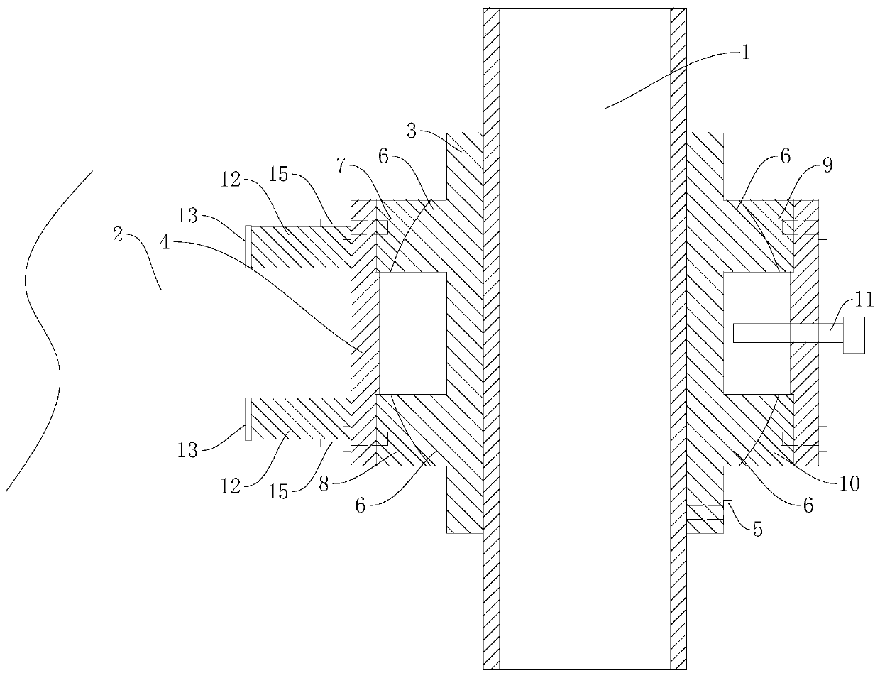
[0024] Such as figure 1 , figure 2 As shown, a steel structure node connection structure used in buildings includes a square column 1, a beam 2 and a sliding sleeve 3 fitted outside the square column 1, and one end of the beam 2 connected to the square column 1 is provided with a The connecting sleeve 4 on the outside of the sliding sleeve 3, the sliding sleeve 3 and the connecting sleeve 4 are square tube-shaped, the sliding sleeve 3 can slide along the square column 1, and the sliding sleeve 3 is provided with a device for connecting the sliding sleeve 3 and the square column 1. For the fixed first locking bolt 5, take the position of the beam 2 relative to the square column 1 as the front, and take the axial direction of the square column 1 as the up and down direction, and the front surface and the rear surface of the sliding sleeve 3 are provided with two protrusions...


PUM


Abstract

The invention discloses a steel structure node connecting structure for a building. The structure comprises a square stand column, a cross beam and a sliding sleeve sleeving the square stand column, wherein a connecting sleeve is arranged at one end, being connected with the square stand column, of the cross beam, the sliding sleeve and the connecting sleeve are both square-tube-shaped, the sliding sleeve can slide along the square stand column, two convex rotating supporting seats are arranged on each of the front surface and the rear surface of the sliding sleeve, the front surfaces of the two rotating supporting seats located on the front surface of the sliding sleeve and the rear surfaces of the two rotating supporting seats located on the rear surface of the sliding sleeve are arc-shaped surfaces located on the same one cylindrical surface, the axis of the cylindrical surface is perpendicular to the axis of the square stand column, a corresponding rotating pressing plate is arranged between the connecting sleeve and each rotating supporting seat, and the rotating pressing plates are attached to the arc surfaces of the rotating supporting seats correspondingly. The invention further discloses a connection method of the structure. The structure has the beneficial effects that the connecting sleeve can be rotated by a certain angle relative to the sliding sleeve along the axial line of the cylindrical surface, so that the cross beam has a rotatable degree of freedom, and meanwhile, connecting structures among all steel structural members are stable and reliable.

Description

technical field [0001] The invention relates to the technical field of construction engineering, in particular to a steel structure node connection structure used in construction and a connection method thereof. Background technique [0002] With the construction of new buildings, the force of the space structure system is becoming more and more complex. Especially when building a complex space steel structure system, due to the limitations of the specific structure, for example, the space steel structure is an irregular multi-dimensional structure, and the connection of the components at the nodes is not a horizontal and vertical "cross" connection, and there are also grounds in actual installation. There is a need to adjust the connection angle under working conditions, but the existing node structures are mostly "cross"-shaped connections or fixed angle connections, which do not have the ability to adjust. Forcible installation will also cause internal stress in the node ...

Claims


Application Information

Patent Timeline
Patent Type & Authority Applications(China)
IPC IPC(8): E04B1/24E04B1/58E04B1/98E04H9/02
CPCE04B1/2403E04B1/98E04B2001/2421E04B2001/2439E04H9/021E04H9/023E04H9/024
Inventor 王萍
Owner TANGSHAN SINOMA HEAVY MASCH CO LTD
Learn More