Firm section material connection structure

A technology for connecting structures and profiles, applied in the direction of slender elements, building elements, etc., can solve the problems of cavity 3a, such as bulky, occupying space, panel deformation, etc., and achieve the effect of ingenious structure, fast assembly, and reliable connection

Active Publication Date: 2015-04-29
佛山市三水和美斯金铝业有限公司
View PDF6 Cites 3 Cited by
  • Summary
  • Abstract
  • Description
  • Claims
  • Application Information

AI Technical Summary

Problems solved by technology

But this connection structure has an obvious defect: in order to resist the left and right torque, it has to make two pairs of connection groups (if one is missing, the reverse torque can easily loosen the hook joint, and the abutment plate is not at all can not be blocked), and the upper and lower connecting groups cooperate with the upper and lower right connecting hooks, naturally forming a cavity 3a when combined, the cavity 3a is bulky and takes up space, making it difficult for engineers to design a portable combination Profiles, for example, only one type of "I" type combined profiles needs to be provided in actual work, but according to the design of the double-sided hook connection structure, the "II" type will eventually be produced
And to form a double-sided hook connection structure, it is necessary to apply force to the panels of the left profile unit 1a and the right profile unit 2a, which will easily deform the panels

Method used


Image

  • Firm section material connection structure
  • Firm section material connection structure
  • Firm section material connection structure

Examples


Embodiment 1

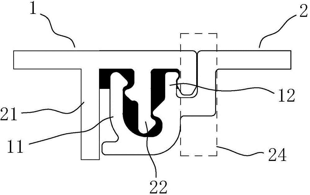
[0021] Embodiment 1: refer to figure 2 , a reliable profile connection structure, including a first profile unit 1 and a second profile unit 2, the first profile unit 1 includes: a first scarfing pit, the left pit wall is a left side plate 21, and the right pit wall It is the center column 22; the second embedding pit, the left pit wall is the center column 22, and the right pit wall is the right side plate body 23 or the right side plate assembly 24; the second profile unit 2 includes: the center column The accommodating pit, the left pit wall is the first connecting hook 11 whose end is fixed in the first embedding pit, the right pit wall is the second connecting hook 12 whose end is fixed in the second embedding pit, and the central column 22 The end of the center column is located in the accommodating pit of the center pillar; the first embedding pit, the accommodating pit of the center pillar and the second embedding pit are arranged sequentially from left to right.

[...

Embodiment 2

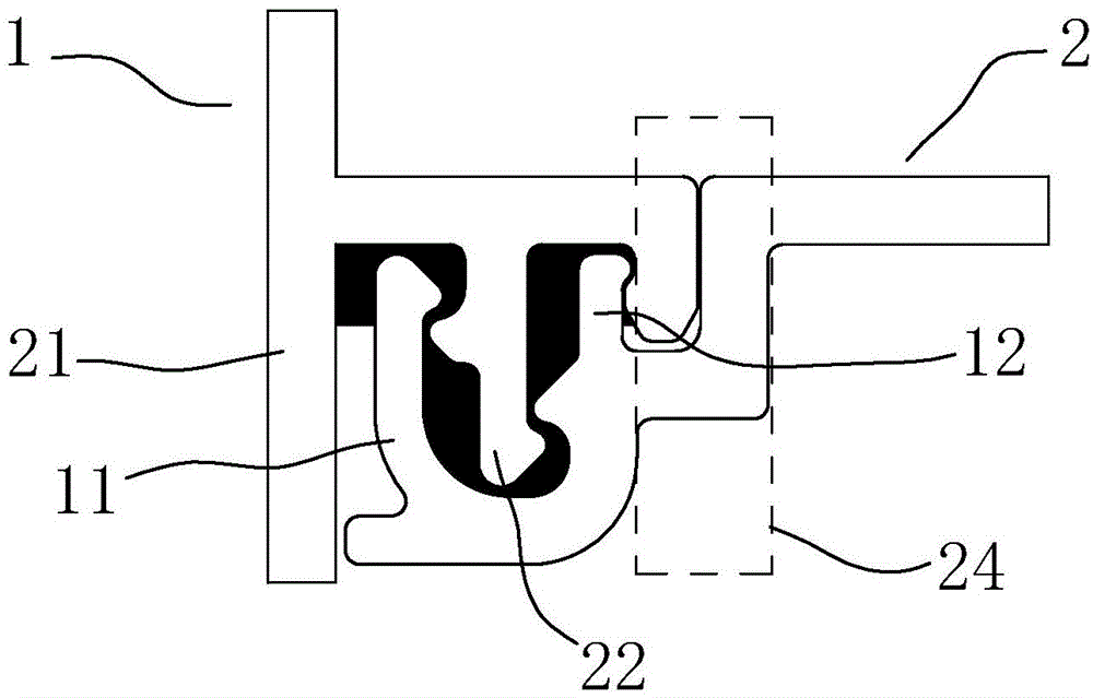
[0025] Embodiment 2: refer to image 3 , the structure of embodiment 2 is basically the same as that of embodiment 1, except that after the design space has been vacated on the left and above the left side panel 21, the left side panel 21 continues to extend upwards so that the whole presents a horizontal "T" The state of the glyph.

Embodiment 3

[0026] Embodiment 3: refer to Figure 4 , the structure of embodiment 3 is basically the same as that of embodiment 1, but the right wall of the second embedding pit is the right side plate body 23, and the right side plate body 23 has such a structure: it is the first profile unit 1 The right end protrudes, and the end of the right plate body 23 abuts against the second profile unit 2 or wraps around the end of the second connecting hook 12 . More specifically, in this embodiment, the end of the right plate body 23 abuts against the second profile unit 2 . In this way, the second profile unit 2 is more difficult to overturn. The left side of the left side plate 21 continues to extend leftwards to become a flat plate, and the right side of the right side plate body 23 also continues to extend rightwards to form a flat plate, and the two form a flat-top composite profile.


PUM


Abstract

The invention discloses a firm section material connection structure. The section material connection structure comprises a first section material unit and a second section material unit, wherein the first section material unit comprises a first embedding pit of which the left wall is a left side plate and the right wall if a middle column, and a second embedding pit of which the left wall of the middle column and the right wall is a right side plate or a right side plate combination; the second section material unit comprises a middle column containing pit; the left wall of the middle column containing pit is a first connecting hook of which the tail end is fixed in the first embedding pit, and the right wall of the middle column containing pit is a second connecting hook of which the tail end is fixed in the second embedding pit; the tail end of the middle column is positioned in the middle column containing pit; the first embedding pit, the middle pit containing pit, and the second embedding pit are arranged in order from left to right. According to the firm section material connection structure, the situation that a traditional dual-edge clip hook structure must forms a cavity is omitted, so that the volume of the connection structure is greatly reduced. The connection structure is ingenious in structure, is safe and stable, is quick and convenient to assemble, and can be widely used in connection structures of section material units.

Description

technical field [0001] The invention relates to a connection structure of profiles in the field of profiles. Background technique [0002] In order to achieve the required profile shape, many profiles are formed by connecting profile units, such as double-color glue injection profiles or spliced ​​profiles. However, for combined profiles, it is often difficult to resist torsion and easy to loosen between its profile units, so most of the existing designs use the connection structure of double-sided hooks. refer to figure 1 , the connection structure of the bilateral hooks, including the left profile unit 1a and the right profile unit 2a, the right profile unit 2a stretches out two right connecting hooks 21a to the left up and down, and the left profile unit 1a stretches out two pairs of connecting groups to the right, respectively The two right connecting hooks 21a are connected, specifically, each pair of connecting groups includes an abutment plate 11a on the outside tha...

Claims


Application Information

Patent Timeline
Patent Type & Authority Applications(China)
IPC IPC(8): F16S3/04
Inventor 朱成祥
Owner 佛山市三水和美斯金铝业有限公司
Why Eureka
Try Eureka