
Compound large-resistance wind-tunnel strain balance

A strain balance and composite technology, applied in aerodynamic tests, measuring devices, instruments, etc., can solve the problems of insufficient resistance bearing capacity, difficult installation of the balance, and insufficient use of the inner cavity space of the model, so as to improve the bearing capacity. , Conducive to the effect of structure and layout optimization design, good practicability and promotion value

Active Publication Date: 2017-05-10
INST OF HIGH SPEED AERODYNAMICS OF CHINA AERODYNAMICS RES & DEV CENT
View PDF10 Cites 10 Cited by
  • Summary
  • Abstract
  • Description
  • Claims
  • Application Information

AI Technical Summary

Problems solved by technology

[0003] In order to overcome the above-mentioned shortcomings of the prior art, the present invention proposes a compound large-resistance wind tunnel strain balance, which aims to solve the difficulty of installing the balance in the aerodynamic measurement of the traditional three-section series rod balance in the return cabin, lander and other models. , Insufficient resistance bearing capacity and the design of the balance did not make full use of the cavity space of the model, providing a compound circuit wind tunnel strain balance and support rod, and completed the accurate measurement of the six components of the model's aerodynamic load

Method used


Image

  • Compound large-resistance wind-tunnel strain balance
  • Compound large-resistance wind-tunnel strain balance
  • Compound large-resistance wind-tunnel strain balance

Examples


Embodiment Construction

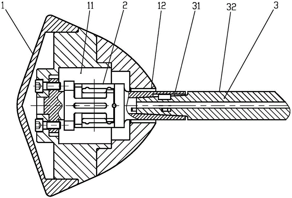
[0014] figure 1 It is an assembly schematic diagram of a compound large resistance wind tunnel strain balance of the present invention. A compound large-resistance wind tunnel strain balance of the present invention mainly includes a compound circuit balance 2 and a support rod 3. The compound circuit balance 2 is connected to the model 1 through a flange, and the square column is positioned. The large-resistance wind tunnel strain balance is matched with the strut through the taper surface, and the wedge is tensioned. The maximum diameter of the strain balance strut of the composite large-resistance wind tunnel is smaller than the minimum diameter inside the model cavity.

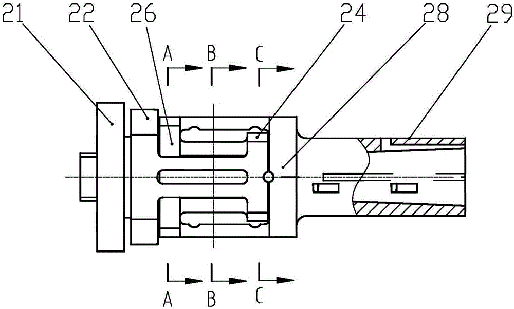
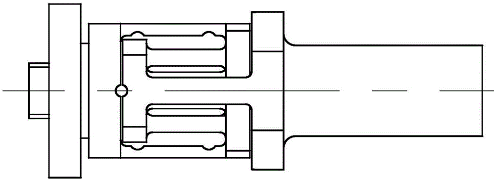
[0015] figure 2 It is a structural schematic diagram of the composite large-resistance wind tunnel strain balance of the present invention. image 3 yes figure 2 The top view of the composite large-resistance wind tunnel strain balance element is placed in the cavity 11 of the model, and six componen...


PUM


Abstract

The invention discloses a compound large-resistance wind-tunnel strain balance which comprises a compound loop balance and a supporting rod. The compound loop balance comprises a free end transition section, a #2 supporting section, a #1 supporting section, a fixed end transition section and a supporting rod connecting section; the supporting rod comprises a cone-shaped connecting section and an equal straight section; the free end transition section is connected to the #2 supporting section through four-column beams (a side force, pitch moment and rolling torque measuring element) on the left and right sides; the fixed end transition section is connected to the #1 supporting section through two-column beams (a lift force and yawing moment measuring element) on the upper and lower sides; the #1 supporting section and the #2 supporting section are connected through a four-column beam (a resistance measuring element) on the inner side; and the supporting rod connecting section is connected to the cone-shaped connecting section of the supporting rod. According to the invention, the balance length is shortened, the diameter of the balance is increased, the carrying capacity of the balance is improved, the testing safety is improved, and the service life of the balance is prolonged.

Description

technical field [0001] The invention belongs to the technical field of aerodynamic force measurement in aerospace dynamometer experiments, especially for the problem of force measurement of aerodynamic models with large lift-drag ratios such as reentry cabins and landers. The circuit structure is compact and the measurement components are arranged, the length of the balance is shortened, the diameter of the balance is increased, the bearing capacity of the resistance element of the balance and the overall rigidity of the balance are improved, and the aerodynamic force of the six components of the model can be better measured. Background technique [0002] When it comes to the aerodynamic measurement of models with large lift-to-drag ratios such as return capsules and landers, due to the large diameter and short length of the models, the resistance load to be measured is often about ten times the lift load, and the load matching It is difficult and requires high measurement a...

Claims


Application Information

Patent Timeline
Patent Type & Authority Applications(China)
IPC IPC(8): G01M9/06
CPCG01M9/062Y02T90/00
Inventor 王树民马涛吴勇航潘华烨向光伟刘大伟贾巍谭显慧杜昕
Owner INST OF HIGH SPEED AERODYNAMICS OF CHINA AERODYNAMICS RES & DEV CENT
Learn More