Electronically-controlled common rail heavy oil injector

A fuel injector and common rail technology, applied in the field of electronically controlled common rail fuel injectors, can solve the problems of large volume of the inner booster structure, interference, fluctuation of servo oil pressure, etc., to avoid corrosion and thermal damage, Improve work stability and save installation space

Active Publication Date: 2019-12-20
CHONGQING HONGJIANG MACHINERY
View PDF7 Cites 9 Cited by
  • Summary
  • Abstract
  • Description
  • Claims
  • Application Information

AI Technical Summary

Problems solved by technology

The application of servo oil prevents heavy oil and electronic components from contacting each other. However, the pressure of servo oil is much lower than that of fuel oil. The volume of the pressurized structure inside the servo oil driver is large, so that the external servo oil driver occupies a relatively large space, and the space layout is difficult.
Therefore, multiple fuel injectors on the same cylinder can often only share one servo oil driver, resulting in the fuel injection between the fuel injectors being unable to be independent of each other and interference
At the same time, the movement of the exhaust valve causes the servo oil pressure to fluctuate, which in turn affects the working response of the servo oil driver and indirectly affects the consistency of each injection of the injector.
In addition, the servo oil driver needs to be arranged far away from the injector due to its large volume, causing a large delay in control

Method used


Image

  • Electronically-controlled common rail heavy oil injector
  • Electronically-controlled common rail heavy oil injector
  • Electronically-controlled common rail heavy oil injector

Examples


Embodiment Construction

[0032] The present invention will be described in detail below in conjunction with the accompanying drawings.

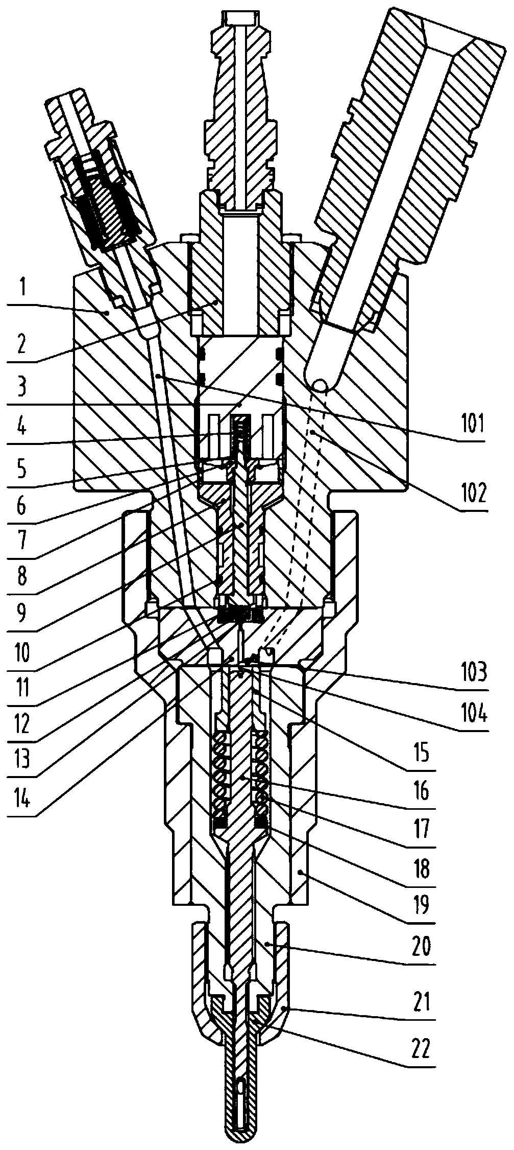
[0033] figure 1 Shown is an electronically controlled common rail heavy fuel injector with a specific structure, which includes three parts: the injector body, the electro-hydraulic control component, and the nozzle component.

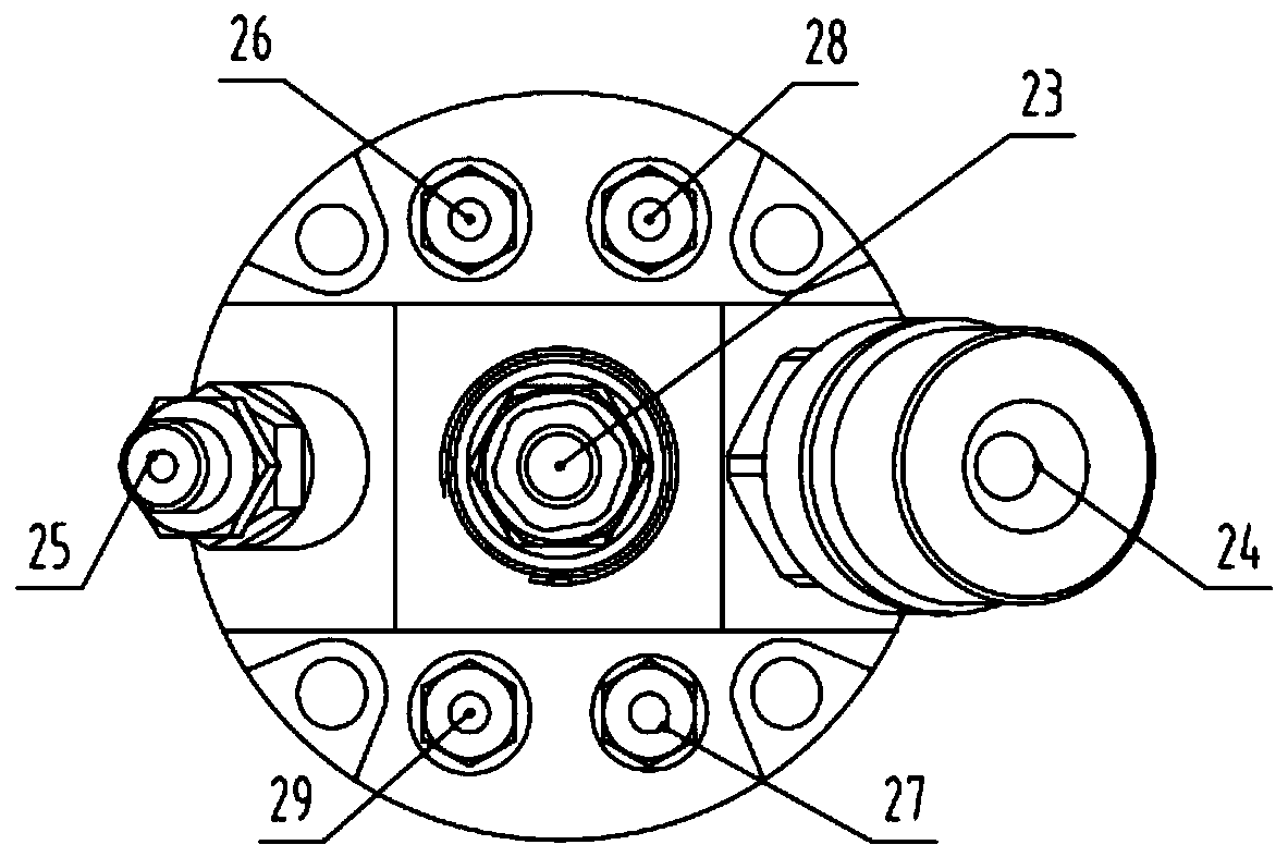
[0034] combinefigure 1 with figure 2 It can be seen that an electronic interface (23) is arranged in the middle of the top of the injector body (1) of the fuel injector, and an oil inlet interface (24), a circulating oil interface (25), and a cooling oil inlet interface ( 26), cooling oil outlet port (27), oil return port (28), mixed oil port (29), respectively connected with electromagnet (3) wire end, oil inlet oil passage (102), circulating oil oil passage (101) , cooling oil inlet passage (107), cooling oil return passage (108), fuel oil return passage (105), mixed oil discharge passage (106) are connected.

[0035] The structural com...


PUM


Abstract

The invention relates to an electronically-controlled common rail heavy oil injector which comprises an injector body, an electro-hydraulic control member and a nozzle member. In the electro-hydrauliccontrol member, a ring groove is formed in the middle of the outer side of a guide sleeve, a transverse through hole is formed in the middle of the groove to directly communicate with a middle hole of the guide sleeve, the two sides of the ring groove are provided with seal rings, and the interior of the oil injector is divided into three chambers. A control valve core guide section is provided with three ring grooves, and the second ring groove is in communication with the transverse through hole in the middle of the guide sleeve. An electromagnetic component is in contact with cooling oil,a cooling oil circuit is isolated from a fuel oil circuit by means of dynamic sealing, static sealing and drainage manners, and corroding and thermal damage of heavy oil to electronic components can be effectively prevented; and a sinking groove is formed in the middle of the top end of an orifice plate, a ball valve seat guide sleeve can be sleeved with the sinking groove of the orifice plate tobe in clearance fit with a ball valve seat, and a certain guiding ability for axial movement of the ball valve seat is achieved.

Description

technical field [0001] The invention relates to a high-pressure common rail engine, in particular to an electronically controlled common rail fuel injector. Background technique [0002] As the transportation costs of shipping companies continue to rise, engines that use heavy oil (combustible with low-quality fuel) as fuel have unique advantages in cost reduction. Due to its many impurities, heavy oil is corrosive to parts and prone to stickiness. It is also corrosive to electronic components. At the same time, heavy oil is viscous and requires high temperature heating when used. Excessive oil temperature will shorten the life of electronic components. . How to improve this problem is an important hot spot to improve the service life of heavy oil diesel engines. [0003] The low-speed diesel engine in the prior art requires hydraulic drive for its exhaust valve control, and it is designed with a servo oil channel specially designed to transport the driving oil. Therefore,...

Claims


Application Information

Patent Timeline
Patent Type & Authority Applications(China)
IPC IPC(8): F02M53/04F02M51/06F02M47/02F02M61/10F02M61/16F02M61/18F02M63/00
CPCF02M53/043F02M51/0614F02M47/025F02M61/10F02M61/16F02M61/1886F02M61/1893F02M61/1806F02M63/0036F02M65/008F02M2200/05F02M2200/03F02M61/182F02M63/0017
Inventor 刘洋陈超张朝磊高浪王春文徐辉李栋张荣钢
Owner CHONGQING HONGJIANG MACHINERY
Why Eureka
Try Eureka