Laser for laser cutting machine

A laser cutting machine and laser technology, applied in the field of lasers, can solve the problems of difficult real-time control, explosive perforation of metal materials, low processing efficiency, etc., and achieve the effects of improving light source utilization, fast response time, and fast cutting speed

Active Publication Date: 2016-08-10
沧州领创激光科技有限公司
View PDF5 Cites 1 Cited by
  • Summary
  • Abstract
  • Description
  • Claims
  • Application Information

AI Technical Summary

Problems solved by technology

There is a contradiction between efficiency and yield in the existing laser processing technology, such as perforation. In order to complete the perforation quickly, we hope to use high power to provide greater energy input, but the input energy is too high and it is easy to cause molten pool The violent gasification of the metal material in the medium causes an explosion, which causes the perforation failure, and produces splashes to contaminate the lens
The traditional solution is to preset a relatively low power in the program, and take a long time to complete the piercing to ensure penetration, and reserve high redundancy to ensure the quality and safety of the piercing. This method saves low processing efficiency. , too dependent on past experience and data, and it is difficult to achieve real-time control, because these problems are more prominent when processing new products

Method used


Image

  • Laser for laser cutting machine
  • Laser for laser cutting machine
  • Laser for laser cutting machine

Examples


Embodiment 1

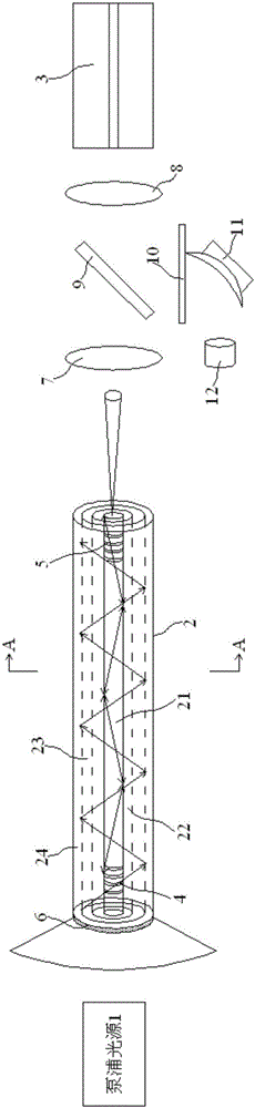
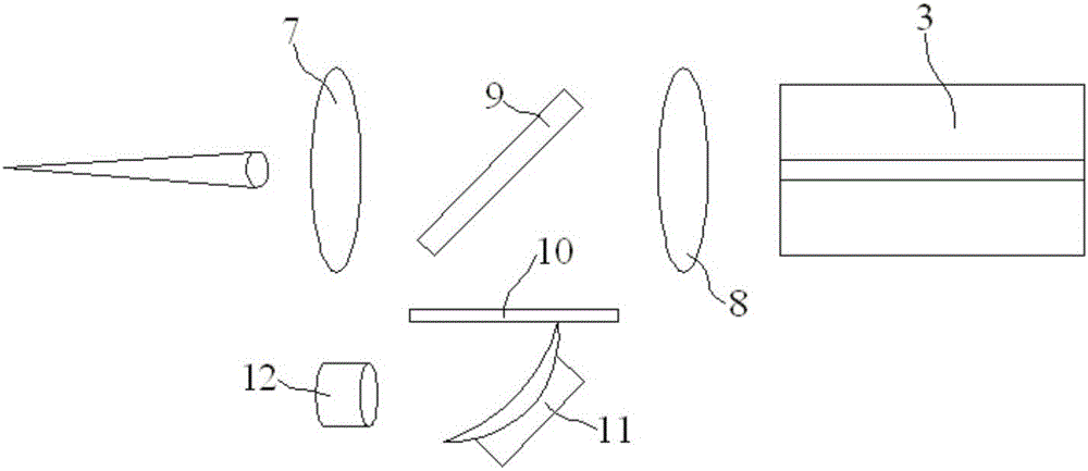
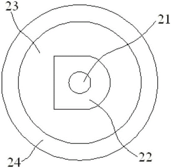
[0017] Embodiment 1: A laser for a laser cutting machine, comprising a pumping light source 1, a cladding fiber 2 and a transmission fiber 3, the pumping light source side pumps or end pumps the cladding fiber 2, the The clad fiber 2 further includes a laser gain medium core 21 located at the center, and the laser gain medium core 21 is sequentially coated with a glass isolation layer 22, a fluorescent material layer 23 and an outer cladding 24 from the inside to the outside. The refractive index of 21 is greater than the refractive index of the glass isolation layer 22, the refractive index of the glass isolation layer 22 is greater than the refractive index of the fluorescent material layer 23, the refractive index of the fluorescent material layer 23 is greater than the refractive index of the outer cladding 24, the cladding optical fiber 2 The input end and the output end are respectively provided with a first fiber Bragg grating 4 and a second fiber Bragg grating 5, and th...

Embodiment 2

[0021] Embodiment 2: A laser for a laser cutting machine, including a pumping light source 1, a cladding fiber 2 and a transmission fiber 3, the pumping light source side pumps or end pumps the cladding fiber 2, the The clad fiber 2 further includes a laser gain medium core 21 located at the center, and the laser gain medium core 21 is sequentially coated with a glass isolation layer 22, a fluorescent material layer 23 and an outer cladding 24 from the inside to the outside. The refractive index of 21 is greater than the refractive index of the glass isolation layer 22, the refractive index of the glass isolation layer 22 is greater than the refractive index of the fluorescent material layer 23, the refractive index of the fluorescent material layer 23 is greater than the refractive index of the outer cladding 24, the cladding optical fiber 2 The input end and the output end are respectively provided with a first fiber Bragg grating 4 and a second fiber Bragg grating 5, and the...


PUM


Abstract

The invention discloses a laser for a laser cutting machine. A clad fiber comprises a laser gain medium fiber core arranged in the middle. The laser gain medium fiber core is wrapped by a glass isolating layer, a fluorescent material layer and an outer cladding layer from the inside out in sequence. The input end and the output end of the clad fiber are provided with a first fiber Bragg grating and a second fiber Bragg grating respectively; the end surface, arranged at the side of a pump light source, of the clad fiber is provided with a tail mirror; a first lens and a second lens are arranged between the clad fiber and a transmission fiber in sequence; a low-pass filter mirror and a focusing mirror are sequentially arranged right under a semi-reflection semi-permeable lens from upward down; the focusing mirror receives reflection light from the semi-reflection semi-permeable lens; an imager is arranged at one side of the focusing mirror and is used for receiving light rays from the focusing mirror; and the cross section of the glass isolating layer is in D shape. Cutting speed is improved; high-power cutting can be tried, and cutting speed is fast and power redundancy is small; and laser energy can be utilized fully.

Description

technical field [0001] The invention relates to a laser used for a laser cutting machine, belonging to the technical field of laser cutting. Background technique [0002] The existing laser cutting process control method is mainly to complete the cutting process through the preset trajectory, speed and power of the program. There is a contradiction between efficiency and yield in the existing laser processing technology, such as perforation. In order to complete the perforation quickly, we hope to use high power to provide greater energy input, but the input energy is too high and it is easy to cause molten pool The violent gasification of the metal material in the medium causes an explosion, which causes the perforation to fail, and produces splashes that contaminate the lens. The traditional solution is to preset a relatively low power in the program, and take a long time to complete the piercing to ensure penetration, and reserve high redundancy to ensure the quality and...

Claims


Application Information

Patent Timeline
Patent Type & Authority Applications(China)
IPC IPC(8): H01S3/067H01S3/0915B23K26/38B23K26/064
CPCB23K26/0643B23K26/0648B23K26/38H01S3/0675H01S3/0915
Inventor 扬·梅埃斯张鹏程
Owner 沧州领创激光科技有限公司
Why Eureka
Try Eureka