Flue gas desulfurization equipment

A technology for desulfurization equipment and flue gas, which is applied in lighting and heating equipment, waste gas exhaust devices, and treatment of combustion products, etc. It can solve the problems of flue gas reversing, inability to completely isolate outage induced draft fans, etc., and achieve the goal of ensuring safety Effect

Active Publication Date: 2018-05-15
CHINA SHENHUA ENERGY CO LTD +2
View PDF6 Cites 0 Cited by
  • Summary
  • Abstract
  • Description
  • Claims
  • Application Information

AI Technical Summary

Problems solved by technology

[0005] The purpose of the present invention is to provide a flue gas desulfurization equipment, which is used to solve the current problem that the induced draft fan cannot be completely isolated and the flue gas is reversed.

Method used


Image

  • Flue gas desulfurization equipment
  • Flue gas desulfurization equipment

Examples


Embodiment Construction

[0035] Specific embodiments of the present invention will be described in detail below in conjunction with the accompanying drawings. It should be understood that the specific embodiments described here are only used to illustrate and explain the present invention, and are not intended to limit the present invention.

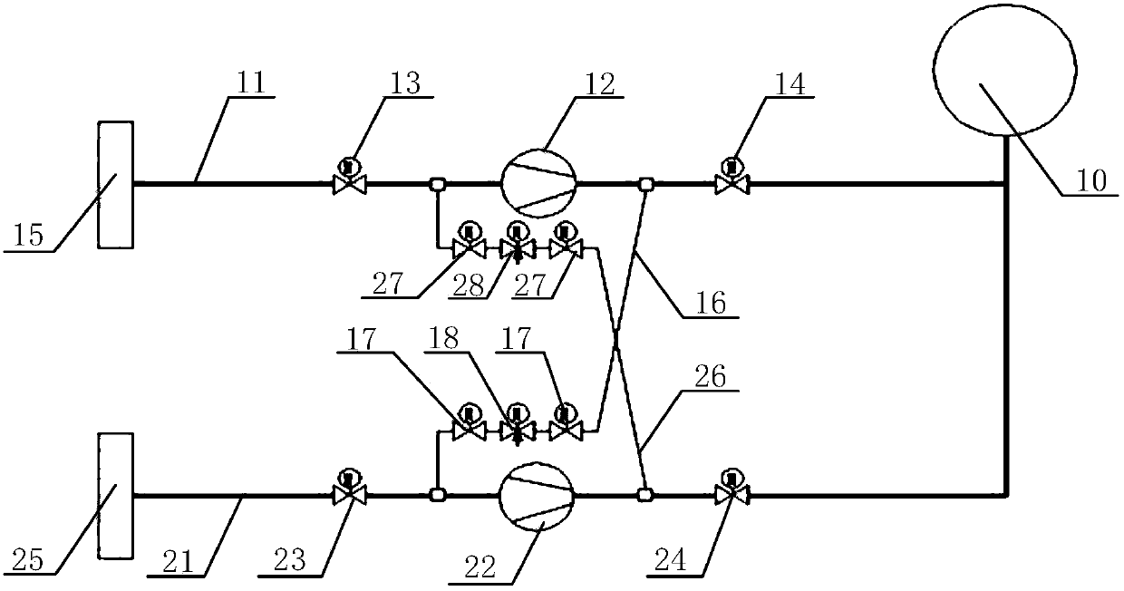
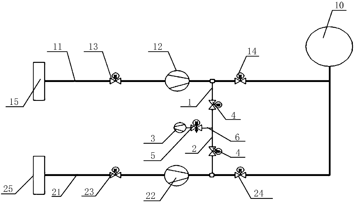
[0036] The present invention provides a flue gas desulfurization equipment, the flue gas desulfurization equipment includes an absorption tower 10 and a first flue 11 connected to the absorption tower 10, the first flue 11 is provided with an outlet facing the absorption tower 10 of the first induced draft fan 12, the first flue 11 is also provided with a first entrance isolation door 13 at the entrance of the first induced draft fan 12 and a first exit isolation door 14 at the exit of the first induced draft fan 12, wherein , between the outlet of the first induced draft fan 12 and the first outlet isolation door 14, a first air suction port is provided, and th...


PUM


Abstract

The invention discloses flue gas desulfurization equipment. The flue gas desulfurization equipment comprises an absorption tower (10) and a first flue (11) connected to the absorption tower (10). A first induced draft fan (12) of which the outlet faces the absorption tower (10) is arranged on the first flue (11), a first inlet isolation door (13) positioned at the inlet of the first induced draft fan (12), and a first outlet isolation door (14) positioned at the outlet of the first induced draft fan (12) are also arranged on the first flue (11), a first exhaust opening is arranged between the outlet of the first induced draft fan (12) and the first outlet isolation door (14), and the first exhaust opening is connected with a suction device used for sucking flue gas at the outlet of the first induced draft fan (12). The flue gas desulfurization equipment can solve the problem that the induced draft fan cannot be completely isolated, and thus flue gas reversely flees at the outlet.

Description

technical field [0001] The invention relates to flue gas treatment technology, in particular to a flue gas desulfurization equipment. Background technique [0002] With the country's emphasis on environmental protection, all power plants canceled and blocked the desulfurization flue gas bypass, and at the same time canceled the booster fan, and adopted the method of increasing and merging to further reduce the power consumption rate of the power plant. [0003] However, in the design mode of the combination of increasing and drawing, due to the need to overcome the desulfurization resistance, the outlet of the induced draft fan is under a slight positive pressure condition, and the outlet of the induced draft fan adopts a baffle-type isolation door because of the large flue, and the baffle-type The isolation door cannot completely isolate the flue gas. Therefore, in the case of isolation and maintenance of the induced draft fan, there is a problem that the flue gas at the ex...

Claims


Application Information

Patent Timeline
Patent Type & Authority Patents(China)
IPC IPC(8): F23J15/02F23J13/08
CPCF23J13/08F23J15/02F23J2215/20
Inventor 林邦春吕智嘉郭为吴公宝
Owner CHINA SHENHUA ENERGY CO LTD
Why Eureka
Try Eureka