
Nitrogen rotational flow sealing heat preservation barrel for wet-type electric dust remover

A technology of wet electrostatic precipitator and heat preservation barrel, which is applied in the field of metallurgy and chemical equipment, can solve the problems of pollution of ceramic bottle heat preservation barrel safety accidents, smoke back-channeling into ceramic bottles and heat preservation barrels, etc., to eliminate potential safety hazards and avoid Safety accidents and the effect of ensuring insulation performance

Pending Publication Date: 2022-05-27
CISDI INFORMATION TECH CO LTD
View PDF5 Cites 0 Cited by
  • Summary
  • Abstract
  • Description
  • Claims
  • Application Information

AI Technical Summary

Problems solved by technology

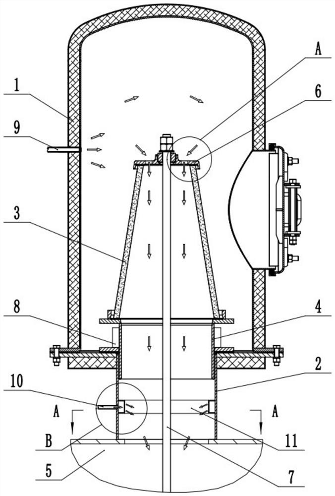
[0004] When the wet electrostatic precipitator is used under negative pressure conditions, the above method and structure can ensure that there will be no dust accumulation and creepage inside the ceramic bottle; but when the wet electrostatic precipitator is under positive pressure conditions, The above method and structure, due to the swirling flow in the flow field, may cause the smoke to flow back into the ceramic bottle, or even into the insulation barrel, and then pollute the ceramic bottle and the insulation barrel, causing corresponding safety accidents, and there are potential safety hazards

Method used


Image

  • Nitrogen rotational flow sealing heat preservation barrel for wet-type electric dust remover
  • Nitrogen rotational flow sealing heat preservation barrel for wet-type electric dust remover
  • Nitrogen rotational flow sealing heat preservation barrel for wet-type electric dust remover

Examples


Embodiment Construction

[0035] The embodiments of the present invention are described below through specific specific examples, and those skilled in the art can easily understand other advantages and effects of the present invention from the contents disclosed in this specification. The present invention can also be implemented or applied through other different specific embodiments, and various details in this specification can also be modified or changed based on different viewpoints and applications without departing from the spirit of the present invention.

[0036]It should be noted that the drawings provided in this embodiment are only to illustrate the basic concept of the present invention in a schematic way, so the drawings only show the components related to the present invention rather than the number, shape and the number of components in actual implementation. For dimension drawing, the type, quantity and proportion of each component can be changed at will in actual implementation, and th...


PUM

PropertyMeasurementUnit
thicknessaaaaaaaaaa
thicknessaaaaaaaaaa

Abstract

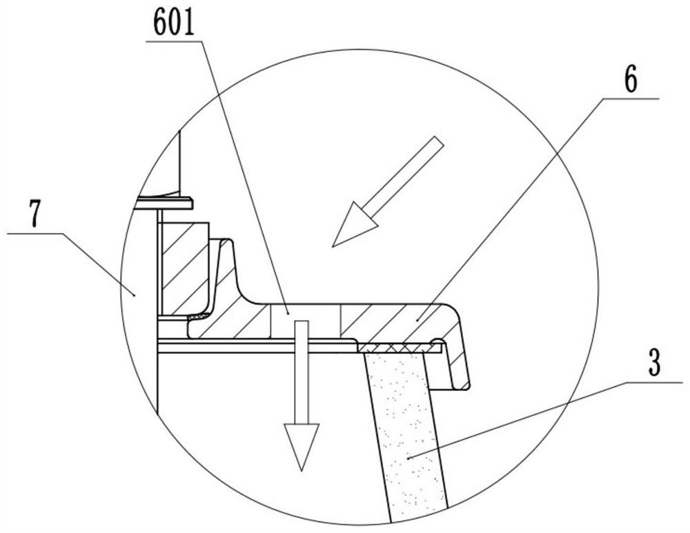
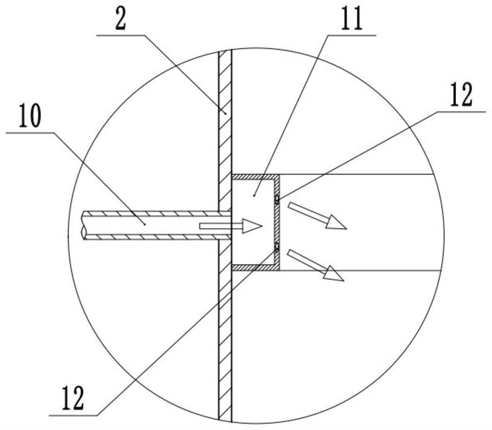
The invention belongs to the field of metallurgical and chemical equipment, and particularly discloses a nitrogen rotational flow sealing heat preservation barrel for a wet-type electric precipitator, which comprises a barrel body, an insulator communicated with the wet-type electric precipitator is arranged in the barrel body, and a nitrogen rotational flow sealing structure is arranged on the barrel body. The nitrogen rotational flow sealing structure comprises a nitrogen supplementing pipe, a nitrogen drainage pipe and a nitrogen storage cavity communicated with the nitrogen drainage pipe, the barrel body comprises a barrel body upper portion and a barrel body base, and a plurality of drainage holes allowing nitrogen to flow into the barrel body base and forming rotational flow in the barrel body base are formed in the side wall of the nitrogen storage cavity. And the rotational flow flows towards the wet-type electric dust remover. The part where nitrogen is introduced into the barrel body is improved, the nitrogen flowing state is optimized, a nitrogen curtain wall is formed in the barrel body, an insulator is isolated from the wet-type electric dust remover, and smoke in the wet-type electric dust remover is prevented from reversely flowing into the insulator, so that it is guaranteed that the insulator is not polluted, the insulation performance of the insulator is guaranteed, and safety accidents are avoided; potential safety hazards are eliminated.

Description

technical field [0001] The invention relates to the fields of metallurgy and chemical equipment, in particular to a nitrogen cyclone sealed thermal insulation barrel for a wet electrostatic precipitator. Background technique [0002] In the process of metallurgical and chemical production, the generated flue gas usually contains a large amount of dust, water vapor or corrosive gas, such as blast furnace flue gas. In order to meet the increasingly stringent environmental protection requirements, the flue gas must be treated accordingly before it is discharged to make it meet the emission standard. [0003] At present, wet electrostatic precipitators are often used in engineering to efficiently remove droplets, dust, etc. in flue gas to achieve deep purification of flue gas. In the wet electrostatic precipitator, since the corona electrode system of the electrostatic precipitator is a high-voltage charged body, its suspension support device must be well insulated from the gro...

Claims


Application Information

Patent Timeline
Patent Type & Authority Applications(China)
IPC IPC(8): B03C3/16B03C3/34
CPCB03C3/16B03C3/34Y02P10/25
Inventor 陶迎钟渝刘国华张瑶杨林邓廷婷
Owner CISDI INFORMATION TECH CO LTD
Learn More