Rectifying tower top reflux temperature adjusting system and process

A technology of reflux temperature and regulation system, which is applied in the direction of distillation regulation/control, piping system, distillation separation, etc. It can solve problems such as unstable operation of equipment, cavitation, and low pressure of reflux tank, so as to ensure safe and stable operation and ensure equipment Stable operation and heat balance maintenance effect

Pending Publication Date: 2022-05-13
SHANXI LUAN COAL BASED CLEAN ENERGY
View PDF0 Cites 0 Cited by
  • Summary
  • Abstract
  • Description
  • Claims
  • Application Information

AI Technical Summary

Problems solved by technology

[0004] However, in the process of reducing the temperature of the reflux tank, the pressure of the reflux tank does not meet the requirements of the working conditions due to the small thermal bypass or the large cooling bypass, and the temperature of the reflux tank cannot be further reduced. At the same time, the pressure of the reflu

Method used


Image

  • Rectifying tower top reflux temperature adjusting system and process
  • Rectifying tower top reflux temperature adjusting system and process

Examples


Embodiment 1

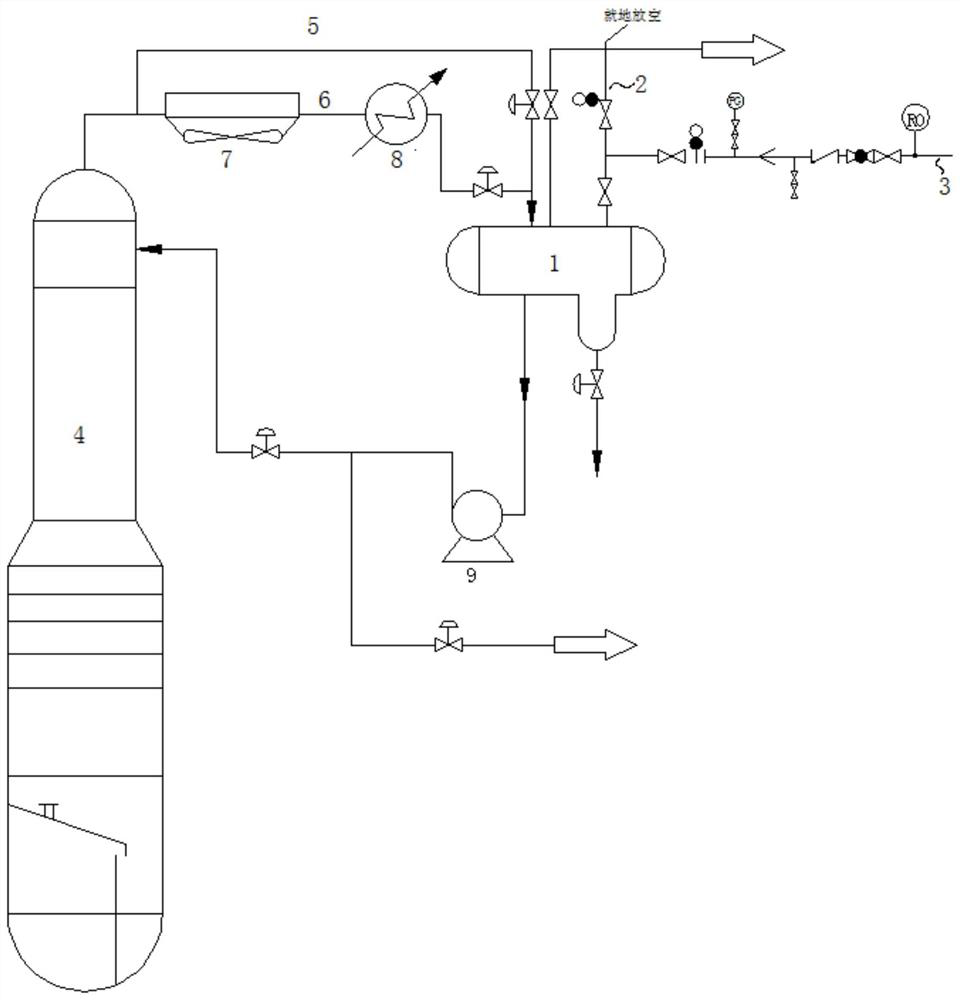
[0039] Such as figure 1 As shown, this embodiment provides a rectification tower top reflux temperature adjustment system, including a temperature control tube group, a reflux tank 1, a vent line 2 and a booster line 3,

[0040] One end of the temperature control tube group is communicated with the top of the rectification tower 4, and the other end is communicated with the inlet of the reflux tank 1, and the reflux port of the reflux tank 1 is communicated with the top of the rectification tower 4. The venting line 2 communicates with the top of the reflux tank 1, and the booster line 3 communicates with the middle of the vent line 2;

[0041] The temperature control tube group includes a hot bypass 5 and a cooling bypass 6 arranged in parallel, the hot bypass 5 is provided with a hot bypass valve, and the cooling bypass 6 is provided with a cold bypass valve.

[0042] Wherein, the bottom side of the return tank 1 is connected with a water diversion part, water and oil are s...

Embodiment 2

[0054] This embodiment provides a rectification tower top reflux temperature adjustment process, which is realized by the rectification tower top reflux temperature adjustment system described in Embodiment 1, including the following steps:

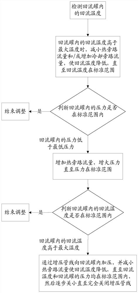
[0055] Step 1: Detect the reflux temperature in the reflux tank 1;

[0056] Step 2: When the reflux temperature in the reflux tank 1 is higher than the maximum temperature, reduce the flow rate of the hot bypass 5 and / or increase the flow rate of the cooling bypass 6 to reduce the reflux temperature until the reflux temperature is within the standard range;

[0057] Step 3: Determine whether the pressure in the return tank 1 is within the standard range:

[0058] If the pressure in the return tank 1 is within the standard range, then end the adjustment;

[0059] If the pressure in the reflux tank 1 is lower than the minimum pressure, increase the flow rate of the thermal bypass 5 and increase the pressure until the pressure is within the...


PUM


Abstract

The invention relates to a rectifying tower top reflux temperature adjusting system and process, the adjusting system comprises a temperature control pipe group, a reflux tank, an emptying pipeline and a pressurizing pipeline, and the pressurizing pipeline is communicated with the middle part of the emptying pipeline at the top of the reflux tank. In the process of reducing the reflux temperature, the pressure needs to be adjusted by increasing the heat bypass flow, but the reflux temperature can be increased, and at the moment, the pressure of the reflux tank at the top of the tower can be increased, the pressure of the reflux tank can be maintained and the heat bypass flow can be reduced by opening a pressurizing pipeline valve, so that the top reflux temperature of the rectifying tower is reduced, and the heat balance of the rectifying tower system is maintained; the material delivery temperature is reduced, and safe and stable operation of a production system is guaranteed; the influence of evacuation and cavitation on the top reflux pump of the rectifying tower is avoided.

Description

technical field [0001] The invention relates to the field of chemical industry, in particular to a rectification tower top reflux temperature adjustment system and process. Background technique [0002] Distillation columns are widely used in chemical production and have long occupied a dominant position in all separation methods. However, in the production process, due to the difference in media and working conditions, the top reflux temperature of the rectification tower is high, which is not conducive to the gas-liquid phase heat transfer balance of the rectification tower; the two do not use the operation of the top reflux pump , when the reflux temperature at the top of the tower is high, it is easy to cause pump evacuation and cavitation, which will affect the operation of the equipment. Products) delivery temperature is high, which cannot meet the safety requirements, especially in summer high temperature weather, which is more prominent and not conducive to the safe...

Claims


Application Information

Patent Timeline
IPC IPC(8): B01D3/42F17D1/00F17D1/08F17D1/14
CPCB01D3/42B01D3/4216B01D3/4222F17D1/00F17D1/08F17D1/14
Inventor 王智白小岗于少华谢海文张文奎张露军裴宏宇董航聂鹏扬陈鹏郭鹏杰林艳君郝伟强赵旭耀王伟国崔保命魏恒苏洁
Owner SHANXI LUAN COAL BASED CLEAN ENERGY
Why Eureka
Try Eureka