Substrate transfer mechanism and subtrate transfer apparatus including same, particle removal method for the subtrate transfer mechanism and apparatus, program for executing the method, and storage medium for storing the program

a transfer mechanism and subtrate technology, applied in the field of substrate transfer mechanisms, can solve the problems of etching deficiency and film quality degradation

Active Publication Date: 2005-11-17
TOKYO ELECTRON LTD
View PDF3 Cites 281 Cited by
  • Summary
  • Abstract
  • Description
  • Claims
  • Application Information

AI Technical Summary

Benefits of technology

[0094] With such a storage medium, since there is formed in a temperature gradient in the mounting table on which the substrate is mounted and the ultrasonic vibrations are applied to the mounting table, the particles are detached from the substrate due to the thermal stress produced at the interface between the substrate and each particle, and are removed from the substrate W by the thermophoretic force applied thereto in a direction moving away from the substrate. Further, the bonding strength between the substrate and the particles becomes weak due to the application of ultrasonic vibrations to the substrate, so that the particles can be assured to be detached and removed from the substrate.

Problems solved by technology

As a result, for example, in an etching process, the attached particles serve as a mask to cause an etching deficiency.
Further, in a film forming process, the attached particles serve as a core to grow, resulting in deterioration in quality of film.

Method used


Image

  • Substrate transfer mechanism and subtrate transfer apparatus including same, particle removal method for the subtrate transfer mechanism and apparatus, program for executing the method, and storage medium for storing the program
  • Substrate transfer mechanism and subtrate transfer apparatus including same, particle removal method for the subtrate transfer mechanism and apparatus, program for executing the method, and storage medium for storing the program
  • Substrate transfer mechanism and subtrate transfer apparatus including same, particle removal method for the subtrate transfer mechanism and apparatus, program for executing the method, and storage medium for storing the program

Examples


Embodiment Construction

[0111] Hereinafter, there will be described preferred embodiments of the present invention with reference to the drawings.

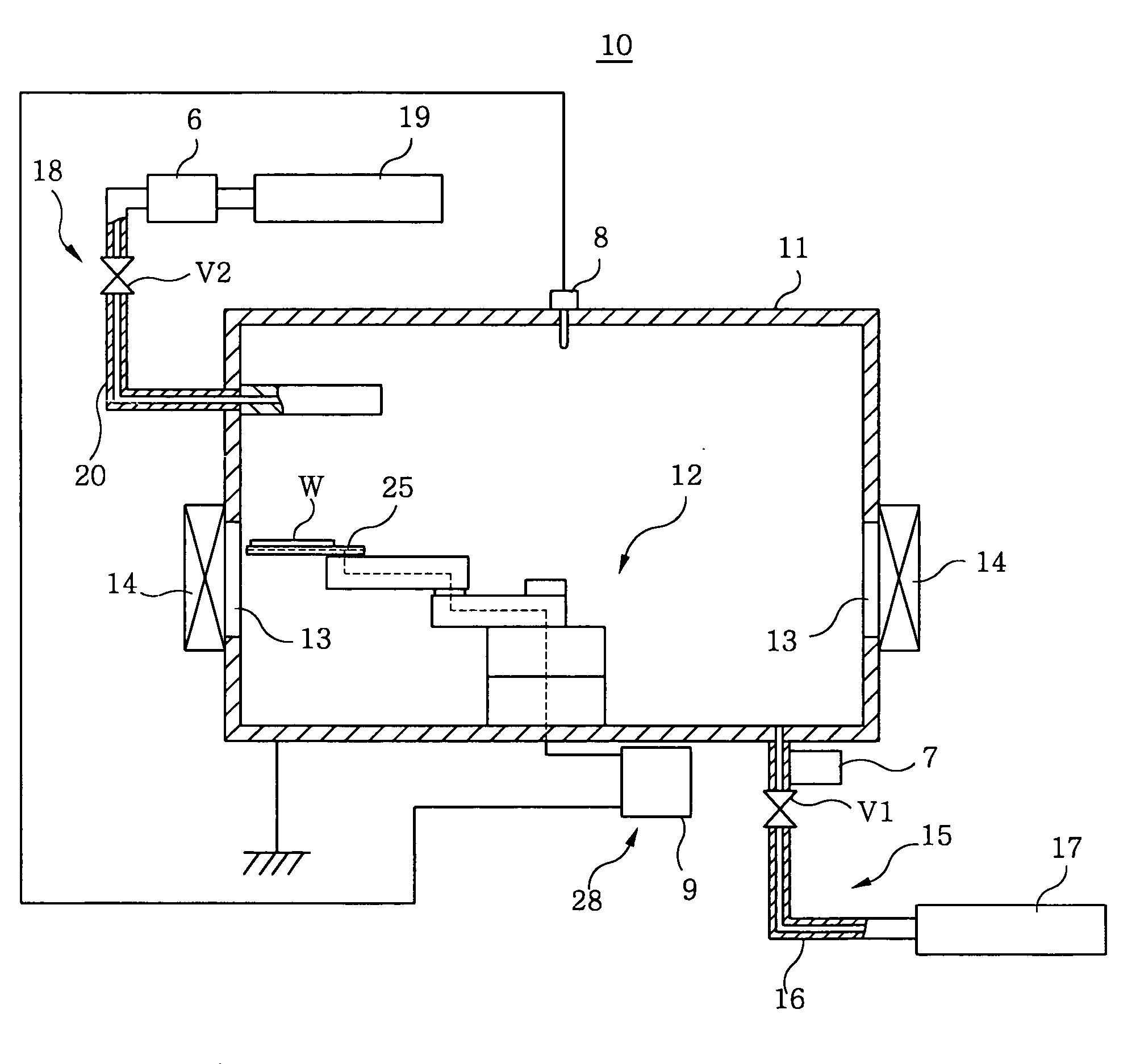
[0112]FIG. 1 is a schematic view showing configurations of a substrate transfer apparatus in accordance with a first preferred embodiment of the present invention.

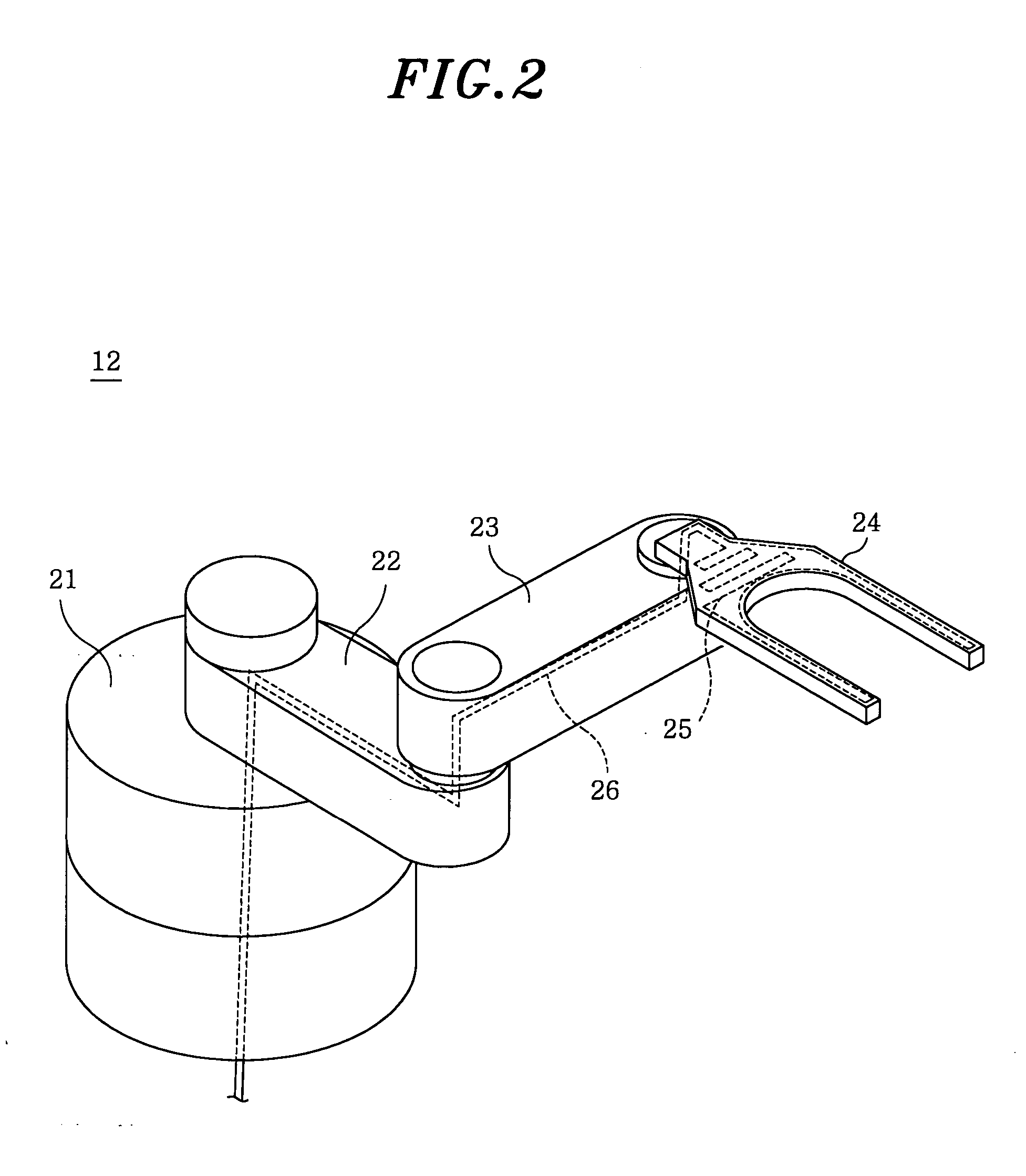
[0113] In FIG. 1, the substrate transfer apparatus 10 includes a box-shaped chamber (accommodating chamber) 11 made of a metal, e.g., aluminum or stainless steel, the chamber 11 being grounded, and a transfer arm (substrate transfer mechanism) 12 for transferring a substrate W into the chamber 11.

[0114] Disposed in a sidewall of the chamber 11 is a loading / unloading gate 13 through which the substrate W is loaded and unloaded by the transfer arm 12 into and from the chamber 11a. The loading / unloading gate 13 is sealed by a gate valve 14 that can be freely opened and closed. Further, an exhaust line (exhaust unit) 15 is connected to a bottom wall of the chamber 11. The exhaust line 15 has an exhaust p...


PUM

PropertyMeasurementUnit
temperatureaaaaaaaaaa
pressureaaaaaaaaaa
diameteraaaaaaaaaa

Abstract

A substrate transfer mechanism for transferring a substrate includes a mounting table on which the substrate is mounted; an arm member connected to the mounting table and moving it. The substrate transfer mechanism further includes a temperature control unit for controlling temperature of the mounting table, wherein the temperature control unit forms a temperature gradient in the mounting table. The temperature control unit includes a detector for detecting temperature in an environment or a chamber in which the substrate transfer mechanism is installed a heater for heating the mounting table and a controller for controlling an operation of the heater based on the temperature in the environment or the chamber detected by the detector.

Description

FIELD OF THE INVENTION [0001] The present invention relates to a substrate transfer mechanism, a substrate transfer apparatus including the substrate transfer mechanism, a particle removal method for each of the substrate transfer mechanism and apparatus, a program for executing the method, and a storage medium for storing the program; and, more particularly, to a substrate transfer mechanism for transferring a substrate to a desired position in order to perform a film forming process, an etching process and the like on the substrate, a substrate transfer apparatus including the substrate transfer mechanism, a particle removal method for each of the substrate transfer mechanism and apparatus, a program for executing the method, and a storage medium for storing the program. BACKGROUND OF THE INVENTION [0002] Conventionally, as a substrate processing system for performing various plasma processing, such as an ion doping process, a film forming process and an etching process, on a subs...

Claims


Application Information

Patent Timeline
Patent Type & Authority Applications(United States)
IPC IPC(8): C23C16/00H01L21/00
CPCH01L21/67103H01L21/67742H01L21/67248
Inventor MORIYA, TSUYOSHINAKAYAMA, HIROYUKIOKUYAMA, KIKUOSHIMADA, MANABU
Owner TOKYO ELECTRON LTD
Why Eureka
Try Eureka