Method of producing porous glass-particle-deposited body and burner for synthesizing glass particles

a technology of porous glass and deposited bodies, which is applied in the direction of glass deposition burners, instruments, manufacturing tools, etc., can solve the problems of reducing the yield of the product, and the conventional method of producing porous glass-particle-deposited bodies by soo

Inactive Publication Date: 2004-09-23
SUMITOMO ELECTRIC IND LTD
View PDF8 Cites 25 Cited by
  • Summary
  • Abstract
  • Description
  • Claims
  • Application Information

AI Technical Summary

Problems solved by technology

However, conventional methods of producing a porous glass-particle-deposited body by the soot process have the following drawback.
As a result, the heat strain produced

Method used


Image

  • Method of producing porous glass-particle-deposited body and burner for synthesizing glass particles
  • Method of producing porous glass-particle-deposited body and burner for synthesizing glass particles
  • Method of producing porous glass-particle-deposited body and burner for synthesizing glass particles

Examples


example 2

[0120] Two types of burners for synthesizing glass particles were used in this example. Burner 1 and Burner 2 had a structure according to the one shown in FIG. 3B with different diameters in the port for feeding a material gas and in the tubular port for feeding a combustion-assisting gas to each other. Porous glass-particle-deposited bodies were produced by using either one of the burners. The same flow rates of the material gas and the combustion-assisting gas issuing from the tubular port were employed for both Burners 1 and 2. However, in Burner 1, the flow velocity of the material gas was 12.15 m / s and that of the combustion-assisting gas issuing from the tubular port was 14.47 m / s (flow velocity ratio: 1.19). In Burner 2, the flow velocity of the material gas was 14.5 m / s and that of the combustion-assisting gas was 18.75 m / s (flow velocity ratio: 1.29).

[0121] During the test, the amount of the deposition of the glass particles on the starting member was measured at intervals...

example 3

[0123] Burner 1 used in Example 2 was also used in this example. Eleven porous glass-particle-deposited bodies were produced under the condition that the flow rate of the combustion-assisting gas issuing from the tubular port is maintained constant and the flow rate of the material gas was varied. In the production of each deposited body, measurement was conducted to obtain the mass of the glass particles deposited during a period of 40 minutes after the start of the deposition of the glass particles on the starting member. The measured result was used to calculate the deposition amount of the glass particles per minute, which is the average deposition rate. The result was used to obtain the ratio to the average deposition rate obtained when the flow velocity of the material gas was 12.15 m / s (Example 2). The ratio is referred to as the relative deposition rate. The relationship between the flow velocity of the material gas (the ratio of the flow velocity of the combustion-assisting...

example 4

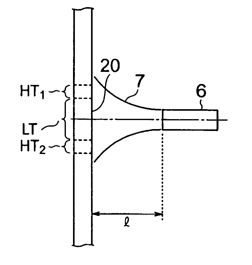
[0125] Burner 1 used in Example 2 was also used in this example to produce porous glass-particle-deposited bodies. In the burner, the following features were maintained constant: the flow velocity of the material gas was 14.5 m / s, the flow velocity of the combustion-assisting gas issuing from the tubular port was 14.47 m / s, and the relative flow velocity as defined in Example 3 was 0.998. However, the distance between the top of the burner and the surface of the starting member was varied to carry out tests. In each test, as with Example 3, measurement was conducted to obtain the average deposition rate of the glass particles during a period of 40 minutes after the start of the production of the deposited body. When the test was conducted with the distance between the top of the burner and the surface of the starting member being 200 mm, the obtained average deposition rate was used as a reference of 1.0. The average deposition rate obtained in each test conducted by varying the dis...


PUM

PropertyMeasurementUnit
Distanceaaaaaaaaaa
Diameteraaaaaaaaaa
Velocityaaaaaaaaaa

Abstract

A method of producing a porous glass-particle-deposited body by effectively depositing the glass particles synthesized by a burner for synthesizing glass particles on a starting member with increased bonding strength between the deposited glass particles and decreased possibility of developing cracks and other problems, and a burner to be used for the production method. In the method of producing the deposited body by depositing the glass particles synthesized by a burner on the surface of the starting member, the glass particle deposition surface has (a) a region that is hit by the center portion of the flame issuing from the burner and (b) another region that has a temperature higher than that of the region hit by the center portion of the flame and that is located at the outside of the region hit by the center portion of the flame.

Description

[0001] 1. Field of the Invention[0002] The present invention relates to a method of producing a porous glass-particle-deposited body, the method comprising the step of depositing glass particles on the surface of a starting member, and to a burner for synthesizing glass particles, the burner being suitable for the production method.[0003] 2. Description of the Background Art[0004] As a method of producing an optical fiber, a production method is known that comprises the steps of synthesizing an optical fiber preform consisting mainly of silica glass, elongating the preform, fire polishing, and drawing. Generally, the optical fiber preform is synthesized by the following steps.[0005] (a) Glass particles are synthesized by using a burner for synthesizing glass particles.[0006] (b) A porous glass-particle-deposited body is produced by depositing the glass particles on the surface of a starting member.[0007] (c) The deposited body is dehydrated and consolidated to obtain a transparent b...

Claims


Application Information

Patent Timeline
IPC IPC(8): G02B6/00C03B8/04C03B37/014C03B37/018
CPCC03B37/01413C03B37/0142C03B2207/06C03B2207/12C03B2207/70C03B2207/36C03B2207/42C03B2207/52C03B2207/62C03B2207/20
Inventor OOISHI, TOSHIHIRONAKAMURA, MOTONORISAKAI, TATSURO
Owner SUMITOMO ELECTRIC IND LTD
Why Eureka
Try Eureka