Method for manufacturing sealed battery and sealed battery manufactured thereby

a manufacturing method and technology for sealed batteries, applied in sustainable manufacturing/processing, cell components, wound/folded electrode electrodes, etc., can solve the problems of increasing the specific requirements for a battery used with these apparatuses, reducing the yield of the product, and hardening the metal, so as to achieve great bonding strength, reduce the unfavorable effect of increasing the bonding strength

Inactive Publication Date: 2007-06-07
SANYO ELECTRIC CO LTD
View PDF4 Cites 25 Cited by
  • Summary
  • Abstract
  • Description
  • Claims
  • Application Information

AI Technical Summary

Benefits of technology

[0027] Further, if the width W of the groove is less than 0.10 mm, the melted metal does not exhibit a great bonding strength between the outer can and the sealing plate. Alternatively, if the width W is more than 0.20 mm, the groove is not filled. This is because a spot diameter of the high energy ray, which is approximately as small as 0.6 mm on a face of the sealing plate to which the ray is radiated, becomes even smaller. This is also because the wall thickness of the outer can is typically as small as 0.20 to 0.30 mm. Therefore, the advantage of increasing the bonding strength is unfavorably reduced.
[0028] Further, if the depth D of the groove is less than 0.10 mm, the groove does not eliminate a heat radiating portion, which would prevent the melted metal from exhibiting a great bonding strength between the outer can and the sealing plate. Alternatively, if the depth D is more than 0.15 mm, heat generated by the high energy ray is not conducted to the interior of the groove. This prevents the melted metal from reaching the deepest part of the groove, which would unfavorably reduce the effect of increasing the bonding strength.
[0029] Further, even if the rise angle θ of the groove toward the top face is 0° (horizontal state), the intended advantage can be achieved. However, when the rise angle θ comes close to parallel to a distribution direction of heat generated by the high energy ray, the effect of eliminating a heat radiation portion is demonstrated to a larger degree. The optimum value of the rise angle θ varies with the material of the sealing plate, the width of the sealing plate flange, the wall thickness of the outer can, the output of the high energy ray, and the like. When the rise angle θ is 0° to 60°, a preferable result can be obtained. Alternatively, when the rise angle θ is more than 60°, the melted metal does not go into the groove, which would unfavorably reduce the effect of increasing the bonding strength.
[0030] In the invention according to claim 4, a laser beam or an electron beam, both of which are typically used as a high energy ray for use in welding, is used. This makes it possible to obtain a prismatic sealed battery that has a weld of excellent reliability and quality.
[0031] According to claims 5 and 6, a sealed battery having strong bonding between the sealing plate the melted metal, and the outer can and the weld with an improved strength can be obtained. The method for manufacturing a sealed battery according to any one of claims 1 to 4 provides a sealed battery configured according to claims 5 and 6.

Problems solved by technology

As use of portable electronic apparatuses rapidly spreads, the specifications required for a battery used with these apparatuses have become increasingly stringent over the years.
However, a crack tends to occur in a weld between the sealing plate and the prismatic outer can, which may significantly reduce the yield of the product.
The volume of metals shrinks when cooled, thus hardening the metal.
This kind of crack occurs not only when the prismatic outer can and the sealing plate are laser welded but also when a circular outer can and a sealing plate are laser welded or when an electron beam is used for welding instead of a laser beam.

Method used


Image

  • Method for manufacturing sealed battery and sealed battery manufactured thereby
  • Method for manufacturing sealed battery and sealed battery manufactured thereby
  • Method for manufacturing sealed battery and sealed battery manufactured thereby

Examples


experimental example

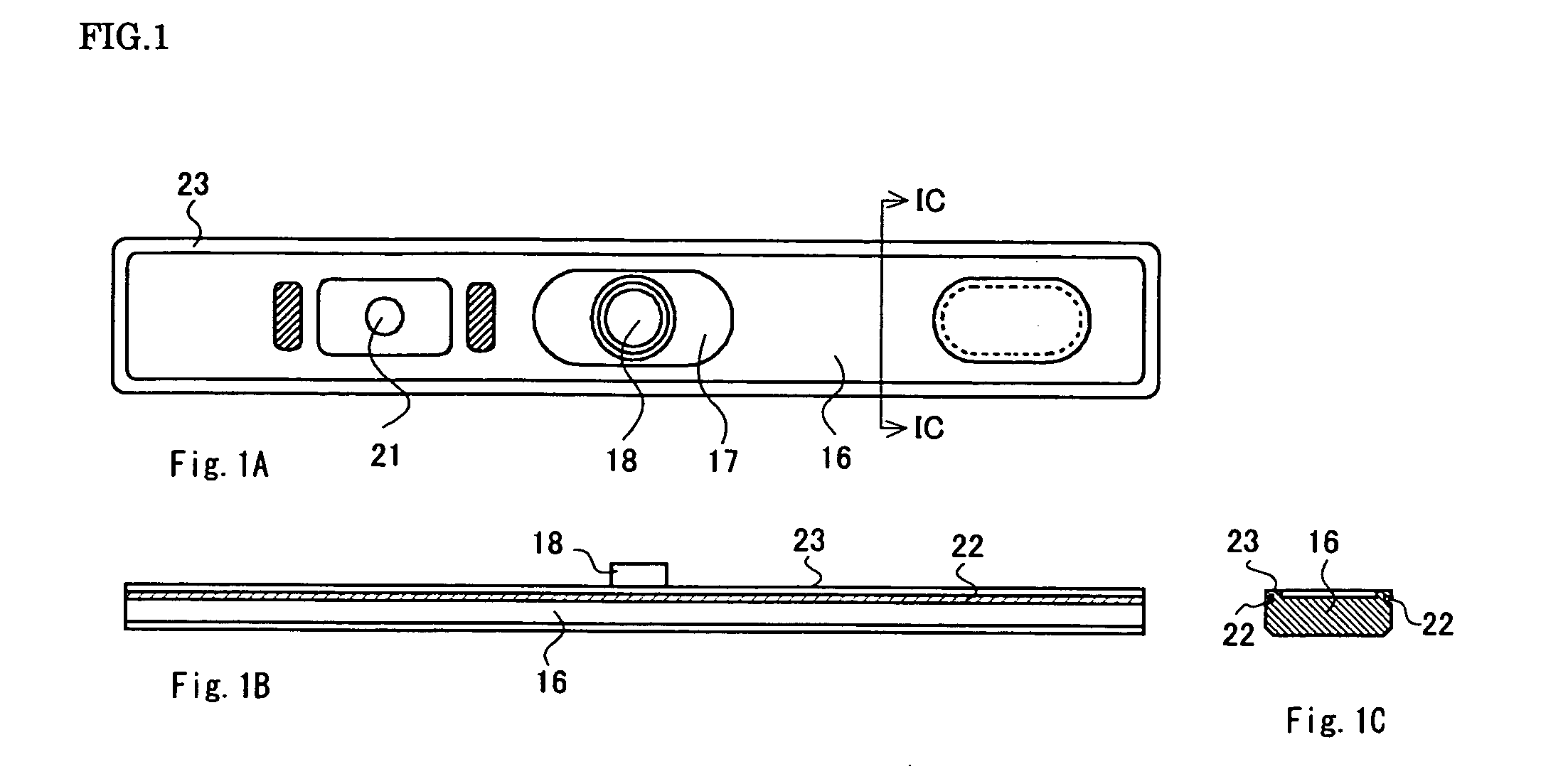
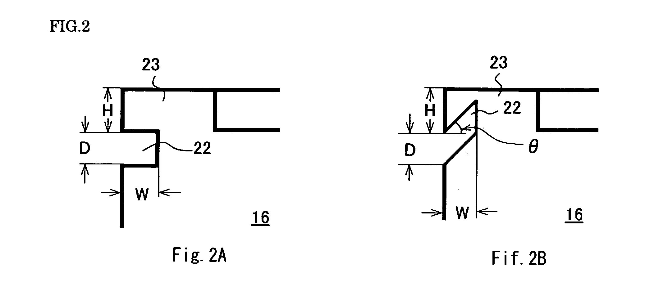
[0041] To begin with, an experimental method that is common to the embodiments and comparative examples is described. As a sealing plate 16 included in a prismatic sealed battery according to first to fourth embodiments, an approximately prismatic sealing plate 16 made of pure aluminum is used as shown in FIGS. 1A to 1C. The sealing plate 16 has a flange 23 on a periphery thereof, a negative terminal 18 mounted at a central part thereof with an insulator 17 therebetween, an electrolyte injection hole 21, and a groove 22 which is formed by cutting a side face of the sealing plate around its perimeter. The first, second, and fourth embodiments use the groove 22 at a rise angle θ of 0° toward the top face of the flange 23 (see FIG. 2A), while the third embodiment uses the groove 22 at a rise angle θ of 45° (see FIG. 2B). Outer dimensions of the sealing plate and dimensions of the groove vary depending on the embodiment. An experiment was performed on each embodiment. As sealing plates ...


PUM

PropertyMeasurementUnit
depthaaaaaaaaaa
widthaaaaaaaaaa
depthaaaaaaaaaa

Abstract

A method for manufacturing a sealed battery according to one embodiment of this invention includes a first step of using an outer can 15 having an opening, and a sealing plate 16 having a flange provided with a groove 22 around or on a part of a fitting face of the sealing plate 16 with the outer can 15, and inserting the sealing plate 16 into the opening of the outer can 15 so that a top face of the outer can 15 is approximately flush with a top face of the flange of the sealing plate 16, and a second step of welding together the outer can 15 and the sealing plate 16 by radiating a high energy ray to the fitting portion therebetween. The invention thus makes it possible to provide a method for manufacturing a sealed battery in which a weld formed by welding a sealing plate fitted into an opening of an outer can of a battery with a laser or other high energy rays has a large breaking strength, and a sealed battery manufactured thereby.

Description

FIELD OF THE INVENTION [0001] The present invention relates to a method for manufacturing a sealed battery and a sealed battery manufactured thereby. The invention particularly relates to a method for manufacturing a sealed battery in which a weld formed by welding a sealing plate fitted into an opening of an outer can of a battery with a laser or other high energy rays has a large breaking strength, and a sealed battery manufactured thereby. BACKGROUND OF THE INVENTION [0002] As use of portable electronic apparatuses rapidly spreads, the specifications required for a battery used with these apparatuses have become increasingly stringent over the years. In particular, such a battery has been required to be small and thin and have a large capacity, an excellent cycle characteristic, and stable performance. In the secondary battery field, attention has been paid to nickel hydrogen batteries and lithium non-aqueous electrolyte batteries for their higher energy density than other kinds ...

Claims


Application Information

Patent Timeline
Patent Type & Authority Applications(United States)
IPC IPC(8): H01M2/08H01M10/04H01M50/184
CPCH01M2/0426H01M2/08Y10T29/49114Y10T29/4911H01M10/0431Y02E60/10H01M50/169Y02P70/50H01M50/184H01M50/103
Inventor YOSHIDA, SATOSHI
Owner SANYO ELECTRIC CO LTD
Why Eureka
Try Eureka