
Eureka
For R&D, Eureka makes reading and utilizing patents & technical documents easy.
Eureka AIR
Designed for self-driven R&D workflows. Generate viable solutions, solve complex R&D challenges, empower your innovation with AI.

Eureka Materials
Designed for material experts only. Revolutionize your material R&D, from search, analyze, to developing new materials.

TechResearch
Generate reliable direction feasibility study reports for your R&D in just a few steps.

TechSeek
Discover and master advanced knowledge NOW. Basics, ideas, possibilities, all at once.

TechMind
As an expert in R&D Theories, TechMind can generates customized viable solutions instantly.

TechRisk
Analyze your overall solution with one click, know your potential R&D risks in advance.

TechMonitor
Get weekly tech updates, stay abreast of the latest tech innovations and key insights.
Top groove water-blocking structure of impervious wall
An anti-seepage wall and water-stop technology, applied in water conservancy projects, marine engineering, construction, etc., can solve problems such as no space for asphalt compression, asphalt water-stop failure, unknown structural damage, etc., to avoid the risk of water-stop failure. Effect
- Summary
- Abstract
- Description
- Claims
- Application Information
AI Technical Summary
Problems solved by technology
Method used
Image

Examples
Embodiment 1
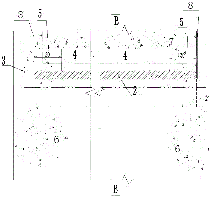
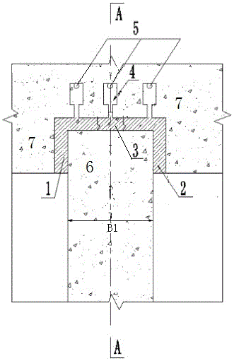
[0023] like figure 1 , figure 2 As shown, the present invention provides a water-stopping structure with grooves at the top of the cutoff wall, which is suitable for the situation where the cutoff wall is arranged at the bottom of buildings such as lock chambers or retaining walls. The present invention comprises the groove 1 that is located at the bottom surface 7 of the building at the top of the anti-seepage wall 6, that is, the bottom surface of the building at the top of the anti-seepage wall 6 is arranged according to the design requirements such as figure 2 The groove 1 in the groove 1 is located between the top of the anti-seepage wall 6 and the bottom surface 7 of the building, and the plastic impermeable material 3 is embedded, and the vertical width of the groove 1 is adapted to the distance between the building and the anti-seepage wall 6. The settlement is poor, and the width of both sides of the groove 1 is adapted to the horizontal displacement between the b...
Embodiment 2
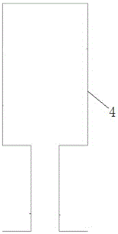
[0025] On the basis of Example 1, the impermeable material 3 is an SR plastic water-stop material, and its indicators meet the design requirements for anti-seepage and various physical property indicators; the several outflow boxes 4 are divided into multiple groups, A group of outflow boxes 4 is arranged between every two adjacent expansion joints 8 on the bottom surface of the building 7, and each group of outflow boxes 4 includes a plurality of outflow boxes 4, and the plurality of outflow boxes 4 are arranged in a row, and the arrangement direction The width direction of the expansion joint 8 and the anti-seepage wall 6 is consistent, the distance between two adjacent outflow boxes 4 in each group of outflow boxes 4 is 0.3 meters, and the number of outflow boxes in each group is determined according to the width B1 of the anti-seepage wall n (n is an integer value of B1 / 0.3m), the outflow box 4 is made of galvanized tinplate. Its main body cavity of described outflow box 4...
PUM
 Abstract
Description
Claims
Application Information
 - R&D Engineer
- R&D Manager
- IP Professional
- Industry Leading Data Capabilities
- Powerful AI technology
- Patent DNA Extraction
Browse by: Latest US Patents, China's latest patents, Technical Efficacy Thesaurus, Application Domain, Technology Topic, Popular Technical Reports.
© 2024 PatSnap. All rights reserved.Legal|Privacy policy|Modern Slavery Act Transparency Statement|Sitemap|About US| Contact US: help@patsnap.com