
Cooling structure of continuously variable transmission

A continuously variable transmission and cooling structure technology, applied in gear lubrication/cooling, transmission parts, belts/chains/gears, etc., can solve the limitation of cooling air discharge, it is difficult to improve the cooling effect of belt-type continuously variable transmission, and it is difficult to form Problems such as air exhaust outlets, to achieve the effect of suppressing the increase of assembly process, suppressing the increase of weight, and improving the cooling effect

Active Publication Date: 2018-07-06
SUZUKI MOTOR CORP
View PDF9 Cites 0 Cited by
  • Summary
  • Abstract
  • Description
  • Claims
  • Application Information

AI Technical Summary

Problems solved by technology

Therefore, it is difficult to form an exhaust port with a large opening area
As a result, the discharge amount of the cooling air is limited, and it is difficult to improve the cooling effect of the belt of the belt-type continuously variable transmission.

Method used


Image

  • Cooling structure of continuously variable transmission
  • Cooling structure of continuously variable transmission
  • Cooling structure of continuously variable transmission

Examples


Embodiment Construction

[0088]Hereinafter, embodiments of the present invention will be described with reference to the drawings. In addition, in the following description, the directions of front, rear, left, right, up, and down are based on the driver seated in the saddle-ride vehicle.

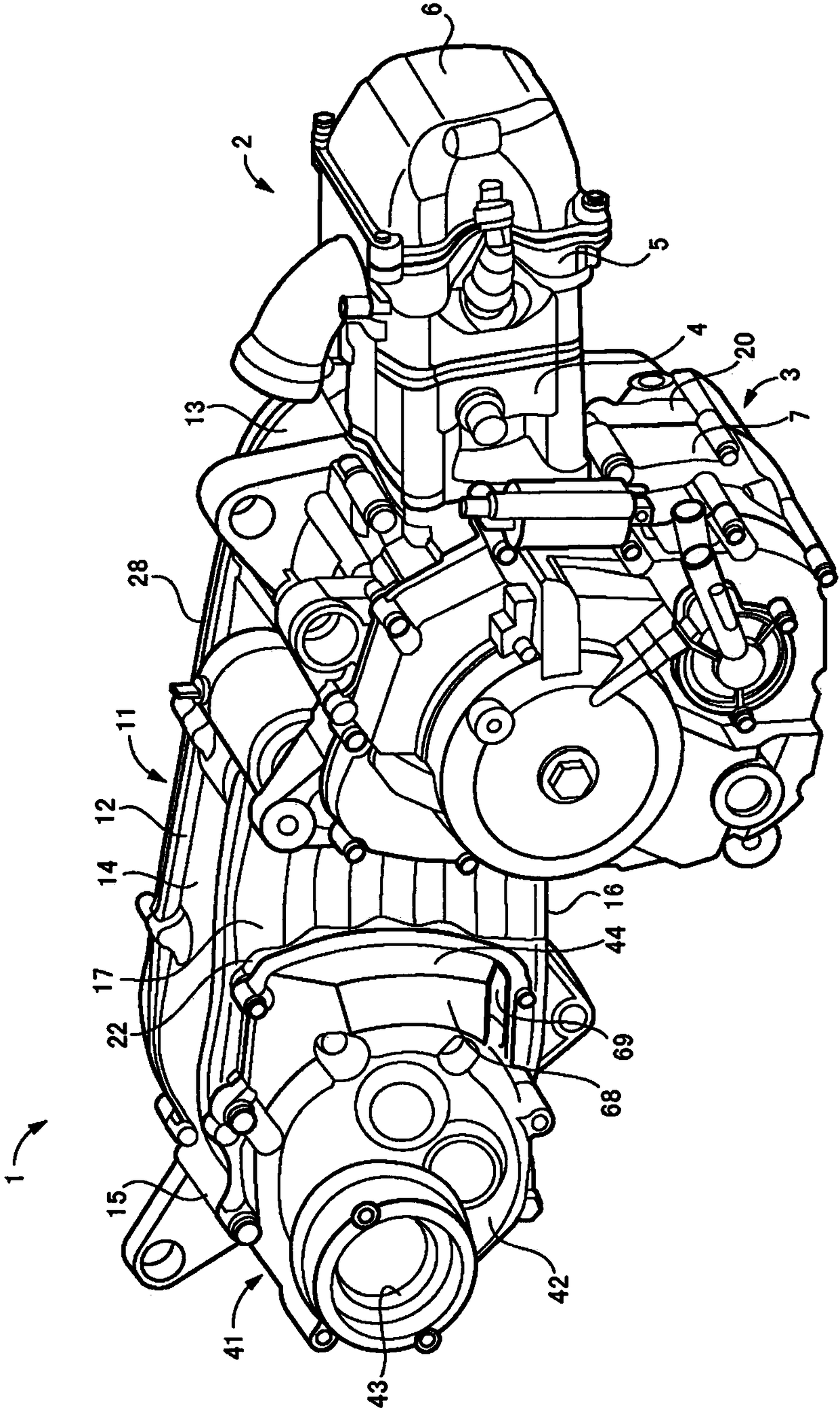
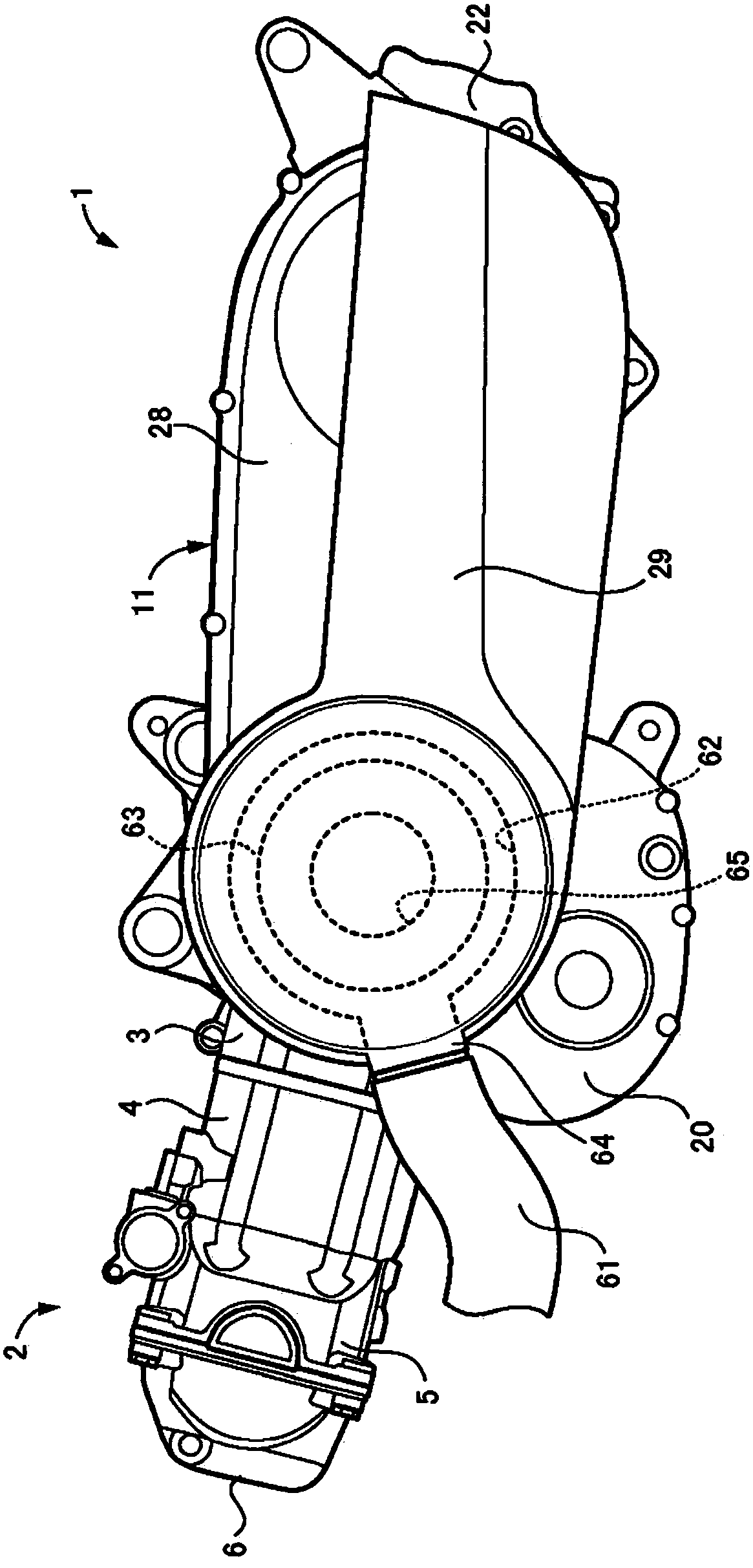
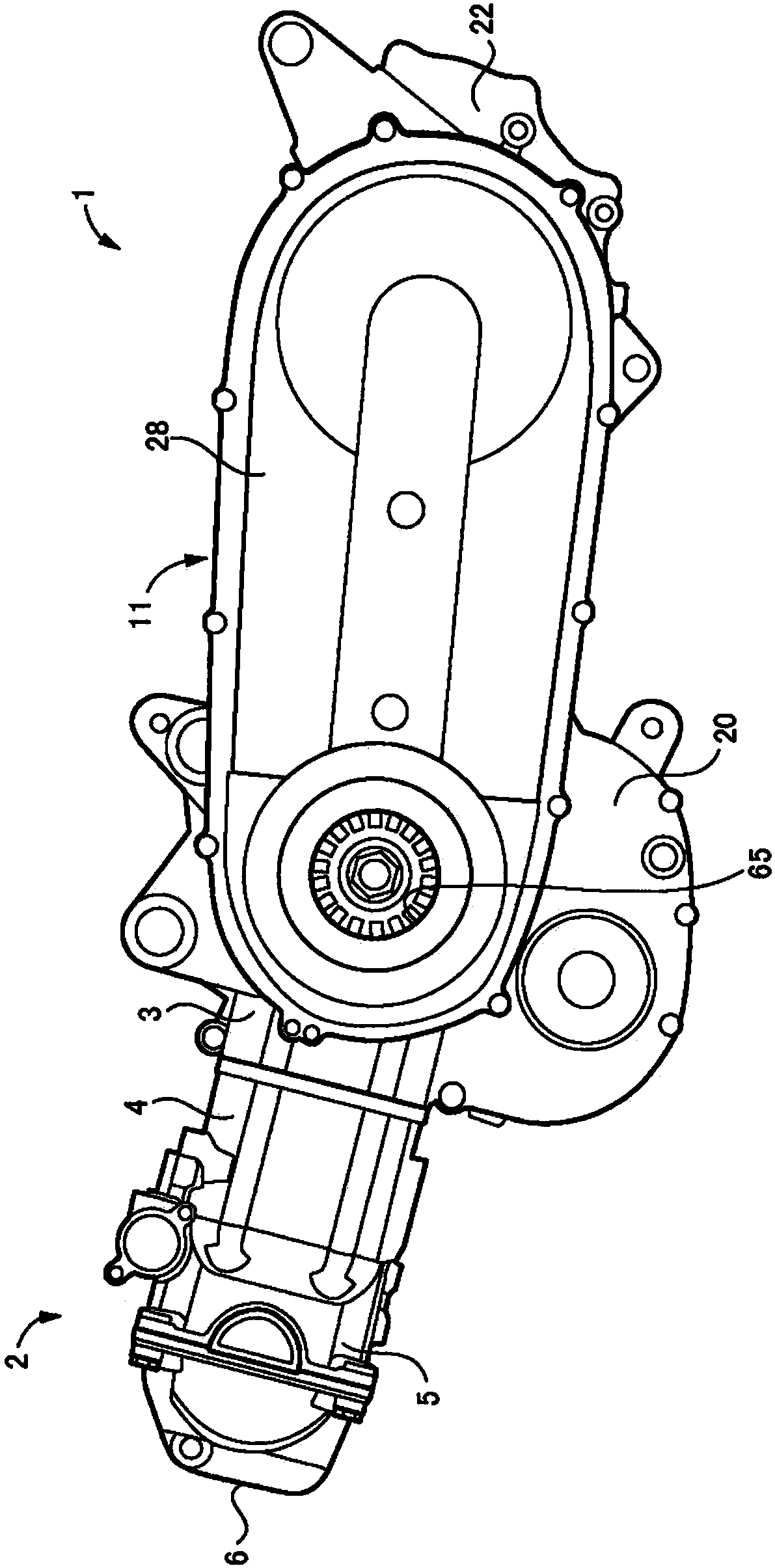
[0089] Figure 1 to Figure 7 An engine unit including a cooling structure such as a belt-type continuously variable transmission according to an embodiment of the present invention is shown. which is, figure 1 means the engine unit as a whole, figure 2 express figure 1 The left side of the engine unit 1 in. image 3 expressed in figure 2 In the engine unit 1 in the state where the side cover 29 and the like have been removed, Figure 4 Furthermore, the state which removed the transmission case cover 28 is shown. Figure 5 express figure 1 on the right side of the engine unit 1 in the Figure 6 expressed in Figure 5 The state in which the gear box case 41 is removed from the engine unit 1 in FIG. F...


PUM


Abstract

In the cooling structure of the continuously variable transmission of the present invention, an exhaust passage for cooling air is formed without adding other components. In addition, an exhaust passage and an air outlet for cooling air are arranged on the inner side of the saddle-ride vehicle in the vehicle width direction, so that the exhaust air The passage area of ​​the passage is increased, or the passage length of the exhaust passage is increased. The cooling air flows in the transmission case (11) to cool the belt of the belt-type continuously variable transmission installed in the transmission case (11), and then flows from the side wall formed on the inside of the transmission case main body (12) in the vehicle width direction. The outlet of (17) flows out in the gear case casing (41). An exhaust passage (68) is formed in the gear box case (41), and an air outlet (69) that opens the exhaust passage (68) to the outside of the engine unit 1 is formed in the gear box case (41). ). The cooling air is discharged to the inner side of the wheel of the rear wheel through the exhaust passage (68) and the exhaust port (69).

Description

technical field [0001] The present invention relates to a cooling structure provided in a continuously variable transmission of a saddle type vehicle such as a scooter. Background technique [0002] A saddle type vehicle such as a scooter includes a unit swing type engine unit. The engine unit has an engine, a belt type continuously variable transmission, a centrifugal clutch, a gear box, and the like as a unit, and further functions as a swing arm for supporting the rear wheel. This engine unit is attached to the body frame of a saddle type vehicle so that it can swing in an up-down direction. [0003] In this engine unit, a transmission case is provided on the left side of the engine unit behind the engine, and a belt-type continuously variable transmission and a centrifugal clutch are accommodated in the transmission case. In the transmission case, the front, rear, upper, lower, and right sides are closed by walls, and the transmission case main body opened on the left ...

Claims


Application Information

Patent Timeline
Patent Type & Authority Patents(China)
IPC IPC(8): F16H57/04
CPCF16H57/0416F16H57/04
Inventor 森正树
Owner SUZUKI MOTOR CORP
Learn More