Method for Reconstructing Echo Information of Pulse System Radar Target in Microwave Anechoic Chamber

A radar target and microwave anechoic chamber technology, which is used in radio wave measurement systems, instruments, etc., can solve problems such as being difficult to be eliminated, target echo signals mixed with transmitted signal components, and occlusion of transmitted signals and target echo signals to achieve target information. The reconstruction results are accurate, the signal occlusion is solved, and the target information reconstruction results are reliable.

Active Publication Date: 2018-06-26
NAT UNIV OF DEFENSE TECH
View PDF4 Cites 0 Cited by
  • Summary
  • Abstract
  • Description
  • Claims
  • Application Information

AI Technical Summary

Problems solved by technology

[0003] Compared with the open domain space where the actual radar is located, the microwave anechoic chamber generally has a limited space distance, and the use of pulse waveforms as radiation signals inside it faces two main technical difficulties: First, in the simultaneous mode of sending and receiving, the transmitting signal and receiving signal will be transmitted between the transmitting and receiving antennas. A very strong electromagnetic field mutual coupling is formed near the mouth surface, resulting in a strong transmit signal component mixed in the target echo signal, which is difficult to be eliminated; second, in the time-sharing mode of sending and receiving, the space size of the microwave anechoic chamber is usually much smaller than the radar pulse width time Electromagnetic waves have gone through the distance, resulting in serious occlusion between the transmitted signal and the target echo signal, that is, the signal of the radar transmission channel has not yet ended, and the target echo signal has returned to the receiving channel

Method used


Image

  • Method for Reconstructing Echo Information of Pulse System Radar Target in Microwave Anechoic Chamber
  • Method for Reconstructing Echo Information of Pulse System Radar Target in Microwave Anechoic Chamber
  • Method for Reconstructing Echo Information of Pulse System Radar Target in Microwave Anechoic Chamber

Examples


Embodiment Construction

[0020] The present invention will be further described below in conjunction with the accompanying drawings. Proceed as follows:

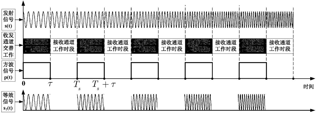
[0021] The first step is to use the intermittent sending and receiving method to realize the pulse signal sending and receiving through the alternate work of the sending and receiving channels.

[0022] Such as figure 1 As shown, assuming that the radar transmit pulse signal is a chirp pulse signal (up frequency modulation), it can be expressed as

[0023]

[0024] Where rect( ) is a rectangular window function, T p is the pulse width, u(t)=exp(jπγt 2 ) is the complex envelope signal, is the unit imaginary number, f 0 is the center frequency, and γ is the chirp frequency.

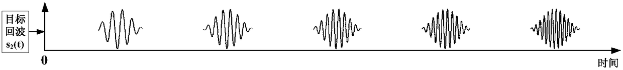
[0025] The intermittent sending and receiving workflow is: first transmit a short pulse signal, switch to the receiving channel before the target echo signal returns, start receiving the target echo signal, and switch to the transmitting channel to continue transmitting...


PUM


Abstract

Provided is a pulse system radar target echo information reconstruction method in a microwave chamber. According to the technical scheme, the method comprises the following steps of radar pulse signal receiving and sending based on intermittent receiving and sending, wherein by means of the intermittent receiving and sending method, no-coupling and no-shielding receiving and sending of a radar pulse signal are achieved through alternative working of a sending channel and a receiving channel, and at this moment, the radar pulse signal receiving and sending process is actually equivalent to the situation of multiplying a square-wave signal p(t) by a radar sending pulse signal s0(t), that is to say, the equivalent radar pulse signal subjected to intermittent receiving and sending can be represented as s1(t)=s0(t).p(t); target echo information obtaining, wherein a radar target time domain impact-response function is supposed to be sigma(t), and after intermittent receiving and sending are conducted, the target echo information can be equivalently represented as s2(t)=sigma(t)*s1(t); target information reconstruction, wherein pulse compression is conducted on the target echo signal s2(t), the target information sh(t) subjected to intermittent receiving and sending is obtained, and accurate reconstruction is conducted on original target information by matching filtering with a time domain windowing signal processing means.

Description

【Technical field】 [0001] The invention belongs to the field of radar detection and simulation, and in particular relates to the technique of sending, receiving and processing pulse-system radar signals in a microwave anechoic chamber, in particular to a method for realizing the reconstruction of pulse-system radar target information in a microwave anechoic chamber. 【Background technique】 [0002] Radar simulation in microwave anechoic chamber has the advantages of strong operability, high repeatability, good confidentiality, and low cost. When performing tasks such as measuring static radar target characteristics in traditional microwave anechoic chambers, signals such as frequency-swept continuous waves are often used to equivalently replace real radar signals. Many modern detection radars use modulated pulse waveforms as transmission signals, and there may be relative motion between the radar and the target. The characteristics of target echo signals corresponding to diffe...

Claims


Application Information

Patent Timeline
Patent Type & Authority Patents(China)
IPC IPC(8): G01S7/40
CPCG01S7/4052
Inventor 潘小义王伟冯德军傅其祥顾赵宇艾小锋刘永才徐乐涛张文明
Owner NAT UNIV OF DEFENSE TECH
Why Eureka
Try Eureka