
Indoor object tracking and positioning system

A technology of tracking and positioning and indoor positioning, which is applied in the field of indoor item tracking and positioning system, can solve problems such as low efficiency, increased installation complexity, hardware cost, high error rate, etc., and achieves easy to use, fast and accurate inventory information, Real-time tracking and positioning effect

Inactive Publication Date: 2016-08-17
WUXI PINGUANG IOT TECH CO LTD
View PDF8 Cites 7 Cited by
  • Summary
  • Abstract
  • Description
  • Claims
  • Application Information

AI Technical Summary

Problems solved by technology

[0002] At present, the widely used indoor monitoring system is the digital monitoring system. The digital monitoring system refers to processing the images collected by the monitoring head into digital signals through software and hardware, and transmitting them to the computer for processing. Compared with traditional monitoring equipment, this system has good The human-computer interaction interface has added functions such as image switching and multi-screen viewing, but when the monitoring personnel need to call to view the screen of an item, they can only search for the position of the item on the monitoring screen manually, and then Retrieve the screen of this item, this method is inefficient, and the manual method will have a relatively high error rate, so it is not suitable for places with relatively high monitoring requirements
On the other hand, when it is necessary to take inventory of indoor monitored items, if only through the digital monitoring system, it is required to detect each item, which requires the number of cameras to be above a certain number, and the increased installed cost Complexity and cost of hardware
In addition, all the monitoring screens are sent back to the monitoring room, and it is necessary to manually count and classify these monitored items. The inventory efficiency is low and the error rate is high

Method used


Image

  • Indoor object tracking and positioning system

Examples


Embodiment Construction

[0007] Combine below figure 1 , to further describe the present invention.

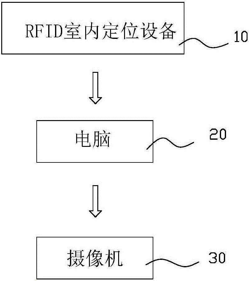
[0008] An indoor object tracking and positioning system includes an RFID indoor positioning device 10 , a computer 20 and a camera 30 , the RFID indoor positioning device 10 is connected to the computer 20 , and the computer 20 is connected to the camera 30 . When the present invention is in use, it is necessary to affix corresponding electronic tags on the indoor items in advance. After the RFID indoor positioning device 10 reads the tag information on the indoor items, it uploads the tag content and position information to the computer 20, and the computer 20 checks these The information is processed and counted, and then translated into the signal of the camera 30 to be transmitted to the camera 30, and the camera 30 is controlled to rotate to the position of the item to take pictures, so that the real-time tracking and positioning of the indoor items can be realized, and the information of the ite...


PUM


Abstract

The invention relates to the technical field of indoor monitoring, and in particular relates to an indoor object tracking and positioning system. The indoor object tracking and positioning system comprises RFID indoor positioning equipment, a computer and a camera; the RFID indoor positioning equipment is connected with the computer; and the computer is connected with the camera. When the indoor object tracking and positioning system disclosed by the invention is used, a corresponding electronic tag is labelled on an indoor object in advance; after reading the tag information on the indoor object, the RFID indoor positioning equipment uploads the tag content and the position information to the computer; the computer processes and counts the information, and then, translates the information into a signal of the camera sent to the camera; the camera is controlled to rotate to the position, where the object is, to shoot; therefore, real-time tracking and positioning of the indoor object can be realized; object information can be checked rapidly and accurately; and the whole system is relatively convenient to use.

Description

technical field [0001] The invention relates to the technical field of indoor monitoring, in particular to an indoor object tracking and positioning system. Background technique [0002] At present, the widely used indoor monitoring system is the digital monitoring system. The digital monitoring system refers to processing the images collected by the monitoring head into digital signals through software and hardware, and transmitting them to the computer for processing. Compared with traditional monitoring equipment, this system has good The human-computer interaction interface has added functions such as image switching and multi-screen viewing, but when the monitoring personnel need to call to view the screen of an item, they can only search for the position of the item on the monitoring screen manually, and then Then call the screen of this item, this method is inefficient, and the manual method will have a relatively high error rate, so it is not suitable for places with...

Claims


Application Information

Patent Timeline
IPC IPC(8): H04N7/18G06K7/00
CPCH04N7/18G06K7/0008
Inventor 蒋宗清田瑞清薛国赟
Owner WUXI PINGUANG IOT TECH CO LTD
Learn More