Developing Device And Image Forming Apparatus Incorporating Same
A developing device and a developer technology, which are applied in the fields of electric recording technology using charge patterns, equipment for electric recording technology using charge patterns, and electrography, can solve problems such as difficult scraper spacing and implementation, and achieve low cost. Effect
- Summary
- Abstract
- Description
- Claims
- Application Information
AI Technical Summary
Problems solved by technology
Method used
Image
Examples
Deformed example 1
[0089] Next, a modified example (hereinafter, this modified example is referred to as "modified example 1") of the configuration in which the round bar scraper 146 is assembled toward the developing cartridge body 144 in the above-mentioned embodiment will be described.
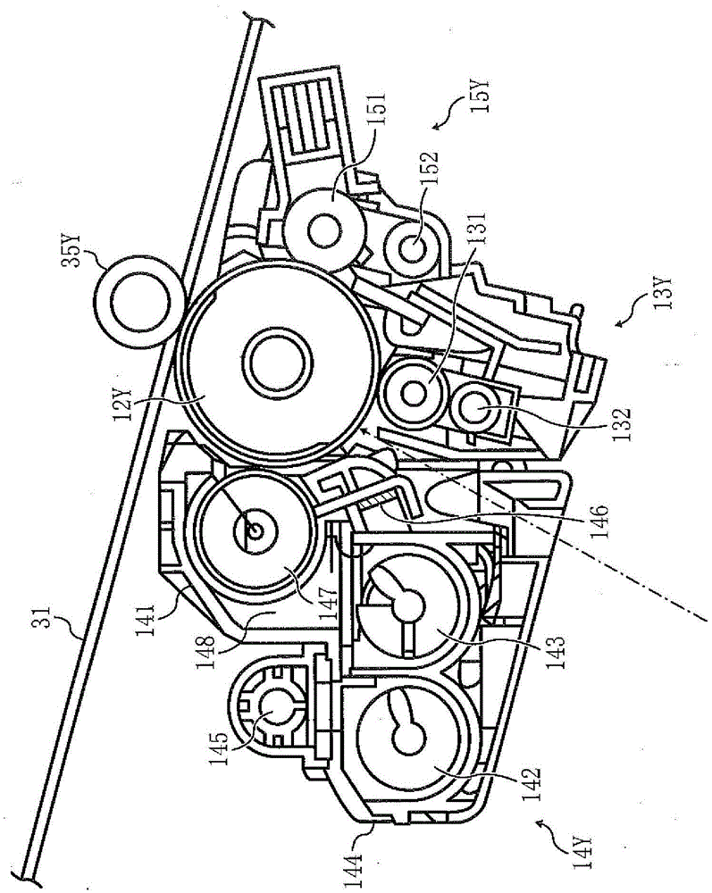
[0090] A rod-shaped developer regulating member such as the round bar blade 146 is generally easier to bend than a flat plate-shaped developer regulating member (blade) as described above. In the present embodiment described above, the vicinity of both ends of the round bar scraper 146 is held by the scraper holders 148 , respectively. Therefore, because of the pressure of the developer, the self-weight of the round bar scraper 146, and the mutual pulling magnetic force of the N2 pole (predetermined limit pole), the center of the long side direction of the round bar scraper 146 is easily displaced after a large displacement. bending. When such bending occurs, the distance DG between the blades near the cente...
Deformed example 2
[0100] Next, another modified example (hereinafter, this modified example is referred to as "modified example 2") of the configuration in which the round bar scraper 146 is assembled toward the developing cartridge body 144 in the above-mentioned embodiment will be described.
[0101]In the operation of installing two or more scraper holders 148 on the holder installation surface 144a respectively, it is necessary to hold the round bar scraper 146 to each scraper holder 148 so that all the scraper holders 148 are positioned in a mutually consistent posture. The round bar scraper 146 is held such that each scraper holding portion 148 holds a designated holding position in the longitudinal direction of the round bar scraper 146 . However, when each scraper holding part 148 is comprised by an independent member, this operation will become complicated.
[0102] Figure 12 (a) to (c) are exploded perspective views of the developing device in the second modification.
[0103] The ...
Deformed example 3
[0110] Next, another modified example of the developing device in the aforementioned embodiment (hereinafter, this modified example will be referred to as “modified example 3”) will be described.
[0111] As described above, a rod-shaped developer regulating member such as the round bar blade 146 is generally easier to bend than a flat plate-shaped developer regulating member (blade). Therefore, problems (instability in the amount of developer conveyed toward the developing area, uneven conveyance of the developer in the direction of the rotational axis of the developing sleeve, etc.) caused by the bending of the round bar blade 146 tend to occur. As a method of suppressing this problem, as described in Modification 1 or Modification 2 above, in addition to increasing the holding portion of the scraper holder 148, 248 for the round bar scraper 146, it is also conceivable to reduce the amount of the round bar scraper 146 so that The method of bending forces.
[0112] In Modifi...
PUM
 Abstract
Description
Claims
Application Information
 - R&D
- Intellectual Property
- Life Sciences
- Materials
- Tech Scout
- Unparalleled Data Quality
- Higher Quality Content
- 60% Fewer Hallucinations
Browse by: Latest US Patents, China's latest patents, Technical Efficacy Thesaurus, Application Domain, Technology Topic, Popular Technical Reports.
© 2025 PatSnap. All rights reserved.Legal|Privacy policy|Modern Slavery Act Transparency Statement|Sitemap|About US| Contact US: help@patsnap.com


