
Included angle and gravity center varying mechanism for tail fins of bio-robotic fish

A technology of fish tail and angle, which is applied in the direction of motor vehicles, ships, special-purpose vessels, etc., can solve the problems of limited energy storage and poor battery life of bionic robot fish, and achieve the effect of stable fish body and high efficiency

Inactive Publication Date: 2016-08-31
SHANGHAI OCEAN UNIV
View PDF6 Cites 7 Cited by
  • Summary
  • Abstract
  • Description
  • Claims
  • Application Information

AI Technical Summary

Problems solved by technology

Limited by the current battery technology, the stored energy is limited, resulting in poor endurance of the bionic robot fish

Method used


Image

  • Included angle and gravity center varying mechanism for tail fins of bio-robotic fish
  • Included angle and gravity center varying mechanism for tail fins of bio-robotic fish
  • Included angle and gravity center varying mechanism for tail fins of bio-robotic fish

Examples


Embodiment Construction

[0016] A bionic robotic fish caudal fin angle and center of gravity changing mechanism of the present invention will be further described in detail below in conjunction with the accompanying drawings.

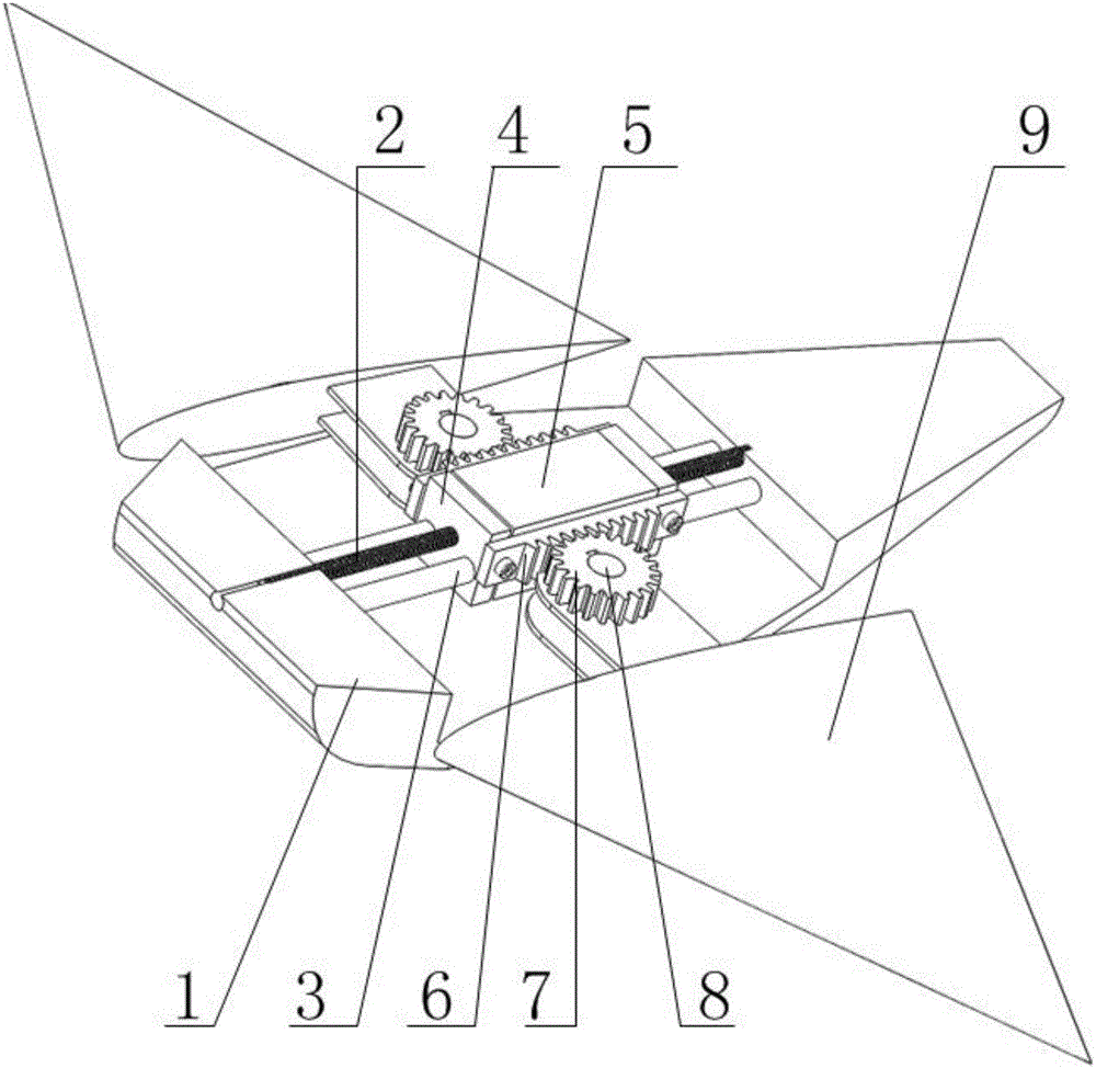
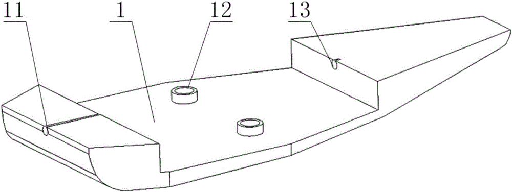
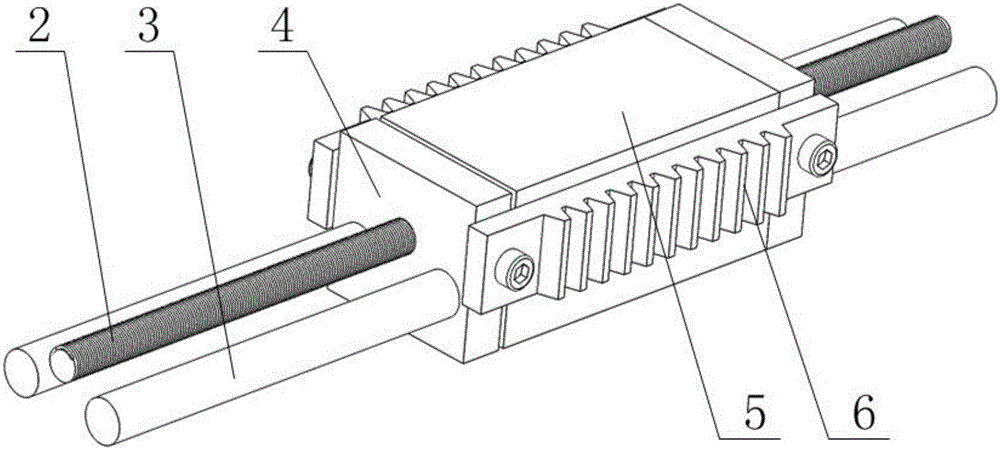
[0017] see figure 1 , figure 2 , image 3 , Figure 4 and Figure 5 , a bionic robot fish caudal fin angle and center of gravity changing mechanism of the invention, comprising a shell (1), a screw (2), a guide rod (3), a slider (4), a counterweight (5), a rack (6), gear (7), shaft (8), tail fin (9), described casing (1) comprises connecting hole (11), fixing sleeve (12) and matching hole (13), and described fixing hole (12 ) is equipped with a bearing, and a screw rod (2) is set between the connecting hole (11) and the matching hole (13), and the screw rod (2) and the guide rod (3) are interspersed in a pair of sliders ( 4) and the counterweight (5), the slider (4) has a screw hole (41), a guide rod hole (42) and an assembly hole (43), the assembly of the slider (4) The...


PUM


Abstract

The invention provides an included angle and gravity center varying mechanism for tail fins of a bio-robotic fish. The mechanism comprises a housing, a lead screw, guide rods, a slide block, a balancing weight, racks, gears, shafts and the tail fins, wherein the guide rods, the racks, the gears and the tail fins are symmetrically distributed about the lead screw. According to the mechanism, the lead screw can be rotated to drive the slide block, the balancing weight and the racks to move forwards and backwards, and on that basis, included angles of the tail fins can be switched between a cruising mode and a charging mode; the balancing weight can move to automatically adjust the gravity center of the bio-robotic fish; when the bio-robotic fish is to enter the cruising state, the lead screw can be clockwise rotated to drive the balancing weight and the racks to move forwards, and the movement of the racks can drive the gears to rotate to enable the tail fins to backwards incline relative to a fish body, so that the gravity center can move forwards, and as a result, the fish body can keep balance and remain stable so as to enter the cruising state; if the bio-robotic fish is to enter a charging state, the lead screw can anticlockwise rotate to drive the balancing weight and the racks to move backwards, and the movement of the racks can drive the gears to rotate to enable the tail fins to be vertical to the fish body, so that the gravity center can move backwards, and as a result, the fish body can keep balanced and remain stable so as to enter the charging state.

Description

technical field [0001] The invention relates to a mechanism for changing the included angle of the caudal fin and the center of gravity of a bionic robotic fish, in particular to the included angle of the caudal fin and the center of gravity of a bionic robotic fish based on oscillating hydrofoil sea (tide) current energy for switching between cruising and charging modes change agency. Background technique [0002] Bionic robotic fish is mainly used in the detection of marine environment and other fields. At present, most robotic fish are driven by motors and work through their own stored energy. Limited by the current battery technology, the stored energy is limited, resulting in poor endurance of the bionic robotic fish. Therefore, in order to prolong the battery life of the bionic robotic fish and further improve its use space, it is necessary to solve the bottleneck problem of energy. If the bionic robotic fish itself can use ocean energy to supplement energy, this pro...

Claims


Application Information

Patent Timeline
Patent Type & Authority Applications(China)
IPC IPC(8): B63G8/26
CPCB63G8/26
Inventor 张丽珍杨朦朦李维维杨加庆邵祺
Owner SHANGHAI OCEAN UNIV
Learn More