a display device

A display device and display panel technology, which is applied to identification devices, instruments, optics, etc., can solve the problems of poor viewing experience, weak intensity, and poor brightness uniformity of the viewer, so as to improve the viewing experience, reduce the brightness difference, improve the The effect of brightness uniformity

Active Publication Date: 2019-03-15
BOE TECH GRP CO LTD
View PDF5 Cites 0 Cited by
  • Summary
  • Abstract
  • Description
  • Claims
  • Application Information

AI Technical Summary

Problems solved by technology

[0003] At present, for an existing display device, the display device has a fixed viewing field concentration area and a non-viewing field concentration area. Concentrated in the field of view concentration area, since the light emitting direction of each area of ​​the display device is usually the same, therefore, the light emitted from the field of view concentration area and falling into the viewer's line of sight has a large number and strong intensity, while the light emitted by the non-view field concentration area The light emitted from the concentrated area of ​​the field and falling into the viewer's line of sight has less light and its intensity is weaker. In the picture seen by the viewer, the brightness of the area corresponding to the concentrated area of ​​the field of view is higher than that corresponding to the area not concentrated in the field of view. The brightness of the area of ​​the area, that is, the brightness uniformity of the picture viewed by the viewer is poor, thus bringing a bad viewing experience to the viewer

Method used


Image

  • a display device
  • a display device
  • a display device

Examples


Embodiment Construction

[0044] In order to further illustrate the display device provided by the embodiment of the present invention, a detailed description will be given below in conjunction with the accompanying drawings.

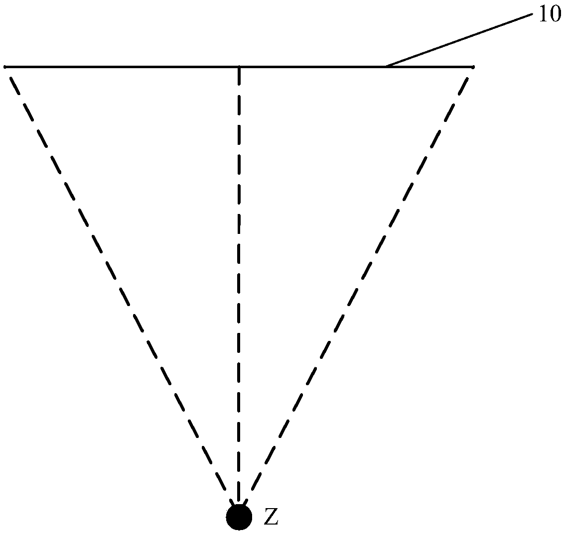
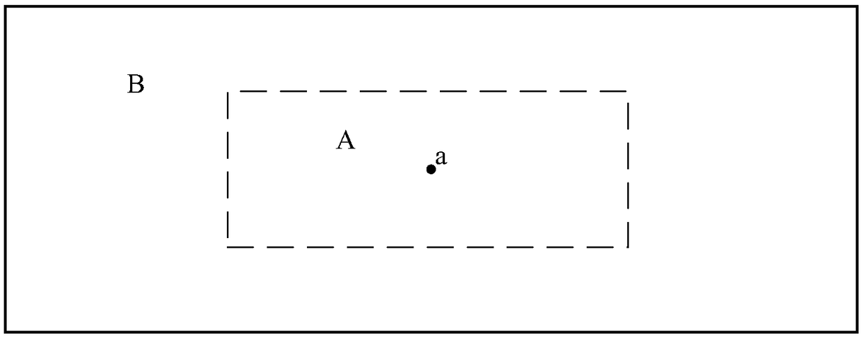
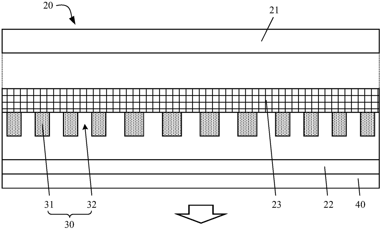
[0045] see Figure 1 to Figure 3 , the display device 10 provided by the embodiment of the present invention includes: a display panel 20, and a grating layer 30 arranged inside the display panel 20 or outside the display panel 20; In the direction of the non-line-of-sight concentration area B of 10, the grating period of the grating layer 30 gradually decreases, and the incident light incident on the grating layer 30 is diffracted in the area corresponding to the non-line-of-sight concentration area B of the display device 10 to obtain The non-zero-order diffracted light is deflected toward the viewer Z's line of sight.

[0046] It is worth noting that the display device 10 provided in the embodiment of the present invention may be a flat display device, a curved display devic...


PUM


Abstract

The invention discloses a display device, relates to the field of display technology, and is used for improving viewing experience of viewers. The display device includes: a display panel, and a grating layer arranged inside or outside the display panel; along the direction from the center of the sight-concentration area of ​​the display device to the non-line-of-sight concentration area of ​​the display device, the grating period of the grating layer After the incident light incident on the grating layer is diffracted in the area corresponding to the non-line-of-sight concentration area of ​​the display device, the obtained non-zero-order diffracted light falls into the viewer's line of sight. The grating period of the grating layer gradually decreases along the direction from the center of the line-of-sight concentrated area to the non-line-of-sight concentrated area, and the incident light is diffracted in the area corresponding to the non-line-of-sight concentrated area of ​​the grating layer and obtained non-zero-order diffracted light Fall into the viewer's line of sight, increase the light quantity and intensity of the light emitted from the non-sight concentration area and fall into the viewer's line of sight, and improve the viewing experience of the viewer.

Description

technical field [0001] The present invention relates to the field of display technology, in particular to a display device. Background technique [0002] A display device is a device used to display text, numbers, symbols, pictures, or images formed by a combination of at least two of the text, numbers, symbols, and pictures. The display device may be a flat display device, a curved display device, a 3D display device, a near-eye display device, an AR / VR display device, and the like. [0003] At present, for an existing display device, the display device has a fixed viewing field concentration area and a non-viewing field concentration area. Concentrated in the field of view concentration area, since the light emitting direction of each area of ​​the display device is usually the same, therefore, the light emitted from the field of view concentration area and falling into the viewer's line of sight has a large number and strong intensity, while the light emitted by the non-...

Claims


Application Information

Patent Timeline
Patent Type & Authority Patents(China)
IPC IPC(8): G02B27/22G09F9/30
CPCG09F9/301G02B30/27G02B5/201G02B5/1819G02B5/1866G02F1/133504G02F2201/305G02F1/133565G02F1/133562G02B5/1842
Inventor 王维杨亚锋陈小川王倩谭纪风高健马新利张粲王灿
Owner BOE TECH GRP CO LTD
Why Eureka
Try Eureka