Hydraulic piling system and cartridge valve thereof

A cartridge valve and hydraulic technology, applied in the direction of fluid pressure actuators, sheet pile walls, servo motor components, etc., can solve the problems of slow control response speed, increased oil circuit complexity, high strike frequency, etc., to achieve guaranteed action Effect

Active Publication Date: 2016-09-07
GUANGDONG LIYUAN HYDRAULIC MACHINERY
View PDF9 Cites 12 Cited by
  • Summary
  • Abstract
  • Description
  • Claims
  • Application Information

AI Technical Summary

Problems solved by technology

In order to achieve large flow control switching, a combination of solenoid valves and ordinary cartridge valves is generally used to form a control valve group to perform reversing switching, but this will inevitably increase the complexity of the oil circuit and reduce the reliability of the system.
After multi-level control, the control response speed is slow, so that the entire hydraulic piling system requires a higher striking frequency

Method used


Image

  • Hydraulic piling system and cartridge valve thereof
  • Hydraulic piling system and cartridge valve thereof
  • Hydraulic piling system and cartridge valve thereof

Examples


Embodiment Construction

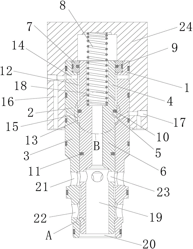
[0032] The present invention will be further described in detail in conjunction with the accompanying drawings and specific embodiments.

[0033] For the convenience of description, the up, down, left, and right directions mentioned below are the same as figure 1 The up, down, left, and right directions are the same.

[0034] combine figure 1 and Figure 4 As shown, a cartridge valve for a hydraulic piling system includes a control cover plate, a valve core, a valve sleeve, a return spring, and a valve core guide sleeve. The spool is divided into the first spool, the second spool and the third spool from top to bottom, and the valve sleeve is divided into the first spool, the second spool from top to bottom. Section valve sleeve, third section valve sleeve. The valve sleeve is provided with an axial through hole, and the axial through hole penetrates from the lower end of the valve sleeve to the upper end of the valve sleeve. Above the end surface is the first section of ...


PUM


Abstract

The invention relates to a cartridge valve used for a hydraulic piling system. The cartridge valve comprises a control cover plate, valve cores, valve sleeves, a reset spring and a valve core guide sleeve. The valve cores are sleeved with axial through holes of the valve sleeves. The first segment valve core and the first segment valve sleeve form a guide cavity. The valve core guide sleeve is arranged on the guide cavity. The second segment valve sleeve is provided with a first valve sleeve oil channel and a second valve sleeve oil channel. The first valve sleeve oil channel communicates with a first seal containing cavity. The second valve sleeve oil channel communicates with a second seal containing cavity. An oil channel cavity is arranged in the third segment valve core. A reset spring cavity used for containing the reset spring is arranged in the first segment valve core. A third oil opening communicates with the oil channel cavity. The invention further relates to the hydraulic piling system and belongs to the technical field of hydraulic piling. According to the cartridge valve, the purposes of large flow communication and high response speed can be achieved. According to the hydraulic piling system, an oil way is simple, and the piling purpose can be achieved very well.

Description

technical field [0001] The invention relates to the technical field of hydraulic piling, in particular to a hydraulic piling system and a cartridge valve thereof. Background technique [0002] Usually, the two-position three-way valve with large flow rate adopts the design form of slide valve. This kind of valve has two functional positions. Half, the flow capacity of the second function position is equivalent to that of the two-way cartridge valve, and the flow capacity of the first function position is smaller than that of the second function position. In the hydraulic system of the hydraulic piling hammer, the differential control oil circuit is adopted, so that when the oil cylinder goes up, the oil discharge from the upper chamber of the oil cylinder is stable. When the oil cylinder goes down, the upper and lower chambers of the oil cylinder need to be connected, and the linear speed reaches above 5m / s. When the upper and lower chambers are connected, the flow through ...

Claims


Application Information

Patent Timeline
Patent Type & Authority Applications(China)
IPC IPC(8): F15B13/02F15B1/02E02D7/06
CPCE02D7/06F15B1/02F15B13/02
Inventor 魏智健莫朝卿李志荣
Owner GUANGDONG LIYUAN HYDRAULIC MACHINERY
Why Eureka
Try Eureka