Rotary compressor and its sliding vane assembly

A sliding vane and component technology, applied in the field of air supply structure, can solve the problem of high cost

Active Publication Date: 2018-06-05
ZHUHAI LANDA COMPRESSOR +1
View PDF9 Cites 0 Cited by
  • Summary
  • Abstract
  • Description
  • Claims
  • Application Information

AI Technical Summary

Problems solved by technology

[0003] Based on this, it is necessary to solve the problem of the high cost of the current two-stage enthalpy increasing technology of the dual-rotor compressor, and provide a sliding vane assembly that can supply air to the rotor compressor to increase the enthalpy in the middle, and also provide a rotor compression machine

Method used


Image

  • Rotary compressor and its sliding vane assembly
  • Rotary compressor and its sliding vane assembly
  • Rotary compressor and its sliding vane assembly

Examples


Embodiment approach

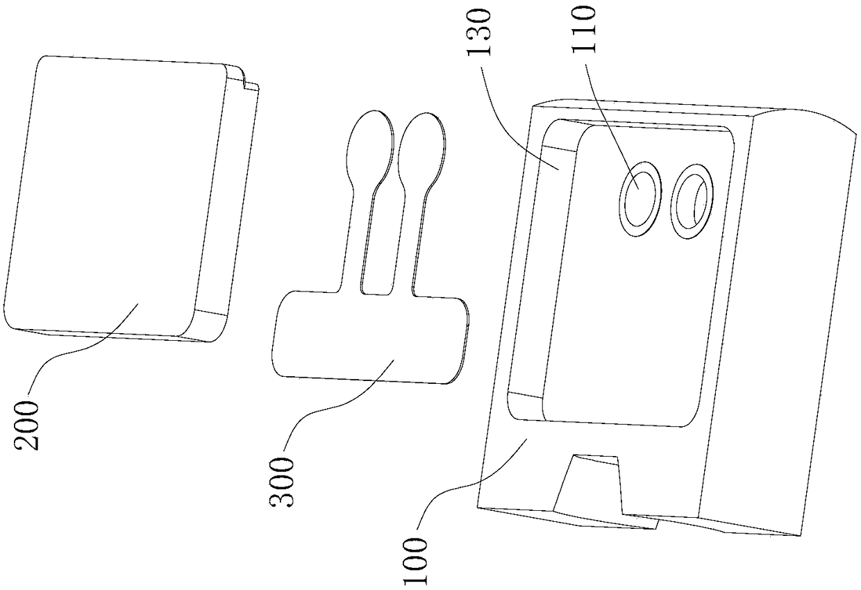
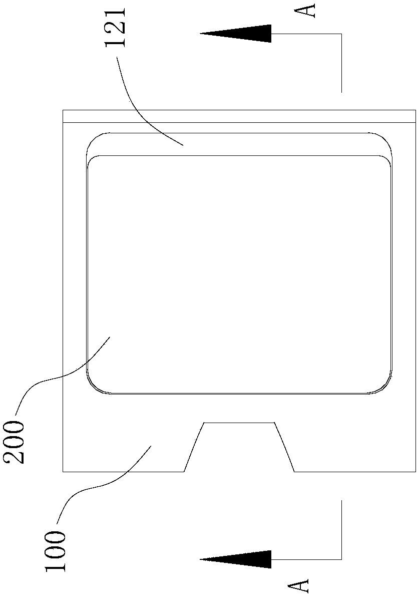
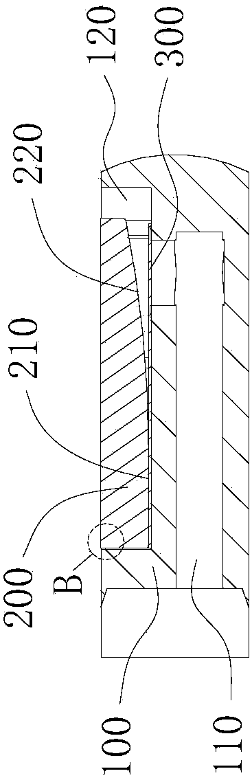
[0054] see Figure 1 to Figure 3 As shown, the first embodiment of the slide assembly of the present invention includes a slide body 100 , a baffle 200 and a valve plate 300 . There is an air supplement channel 110 inside the slider body 100; the baffle plate 200 is fixedly connected to one side of the slider body 100, and a back pressure chamber 120 is formed between the end of the baffle plate 200 and the slider body 100, and the back pressure chamber 120 There is an air supply outlet 121 communicating with the outside world, and the exhaust port of the air supply channel 110 is set corresponding to the back pressure chamber 120; the valve plate 300 is fixedly connected between the sliding plate body 100 and the baffle plate 200, and the movable end of the valve plate 300 It is located in the back pressure chamber 120 and correspondingly arranged on the exhaust port of the supplementary air passage 110; the movable end of the valve plate 300 has two stations for closing and ...


PUM


Abstract

The invention provides a rotor compressor and a slip sheet assembly thereof. The slip sheet assembly comprises a slip sheet body, a baffle and a valve plate, wherein an air supply passage is arranged in the slip sheet body; the baffle is fixedly connected to one side face of the slip sheet body, a back pressure chamber is formed between the end part of the baffle and the slip sheet body, the back pressure chamber has an air supply outlet communicating with the outside, and the exhaust port of the air supply passage is arranged corresponding to the back pressure chamber; the valve plate is fixedly connected between the slip sheet body and the baffle, the movable end of the valve plate is located in the back pressure chamber and is correspondingly arranged on the exhaust port of the air supply passage; and the movable end of the valve plate has two stations for closing and opening the exhaust port of the air supply passage. When the pressure in the air supply passage is greater than the pressure in the back pressure chamber, the valve plate is opened, and the air supply passage supplies air to the back pressure chamber, thus realizing enthalpy increasing by air supply for a compression chamber of a compressor cylinder; and when the pressure in the air supply passage is lower than the pressure in the back pressure chamber, the valve plate is closed, thus preventing compressed gas in the back pressure chamber from flowing back to enter the air supply passage.

Description

technical field [0001] The invention relates to an air supply structure of a rotor compressor, in particular to a rotor compressor sliding vane assembly and a rotor compressor. Background technique [0002] In order to meet the heating performance requirements in cold regions in winter, the current practice is to use the two-stage enthalpy increase technology on the two-rotor compressor, but the cost of this method is relatively high. Contents of the invention [0003] Based on this, it is necessary to solve the problem of the high cost of the current two-stage enthalpy increasing technology of the dual-rotor compressor, and provide a sliding vane assembly that can supply air to the rotor compressor to increase the enthalpy in the middle, and also provide a rotor compression machine. [0004] Above-mentioned purpose realizes through following technical scheme: [0005] A slide assembly, comprising: [0006] A slide body, the slide body is provided with an air supply cha...

Claims


Application Information

Patent Timeline
Patent Type & Authority Patents(China)
IPC IPC(8): F04C18/356F04C29/12
CPCF04C18/356F04C29/124
Inventor 谢利昌刘达炜高永红吕浩福
Owner ZHUHAI LANDA COMPRESSOR
Why Eureka
Try Eureka