
Ejector enhanced quasi-two-stage compression type circulating system

A circulation system and injector technology, applied in the field of quasi-two-stage compression circulation system, can solve problems such as the decrease of the effective use area of ​​the heat exchanger, the increase of irreversible loss, and the increase of the size of the heat exchanger, so as to ensure energy saving and Stability, improving utilization, and reducing the effect of suction specific volume

Active Publication Date: 2022-01-07
SHANDONG UNIV
View PDF8 Cites 0 Cited by
  • Summary
  • Abstract
  • Description
  • Claims
  • Application Information

AI Technical Summary

Problems solved by technology

However, as the evaporation temperature decreases, the irreversible loss of throttling increases, and too much flash gas enters the evaporator, resulting in a decrease in the effective use area of ​​the heat exchanger and an increase in the size of the heat exchanger
[0009] Patent CN110274403A discloses a quasi-two-stage compression cycle system with injector synergy, which improves the suction inlet pressure of the compressor and reduces the power consumption of the compressor. It is difficult to find a suitable air supply point when operating under variable operating conditions only by adjusting the throttle valve during operation

Method used


Image

  • Ejector enhanced quasi-two-stage compression type circulating system
  • Ejector enhanced quasi-two-stage compression type circulating system
  • Ejector enhanced quasi-two-stage compression type circulating system

Examples


Embodiment 1

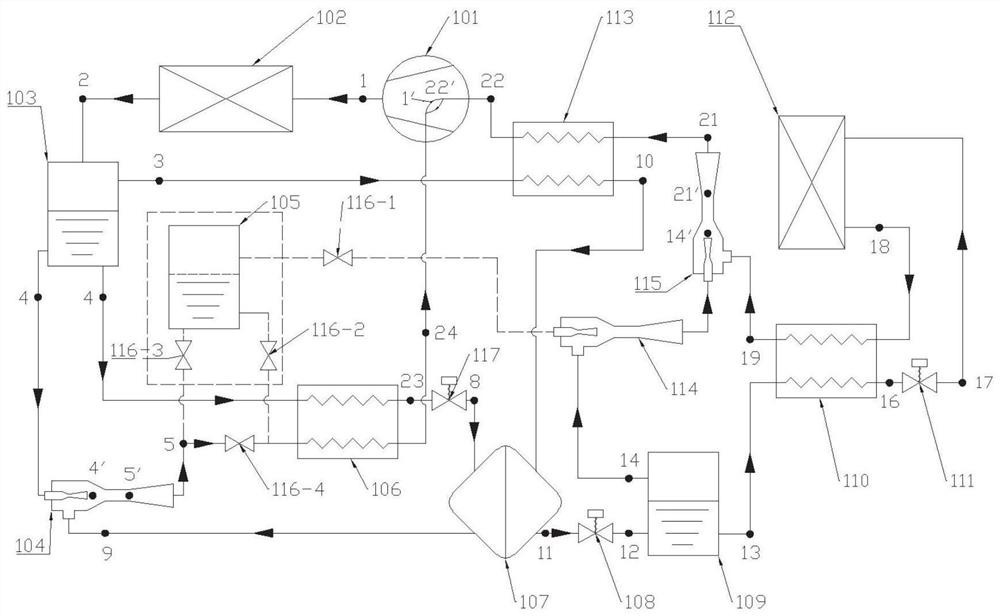
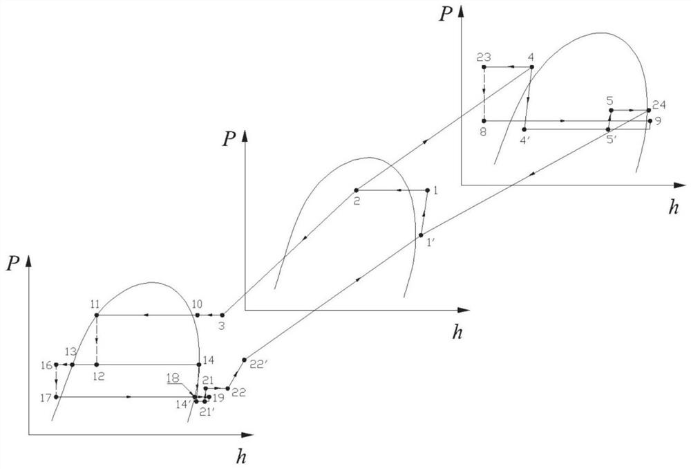
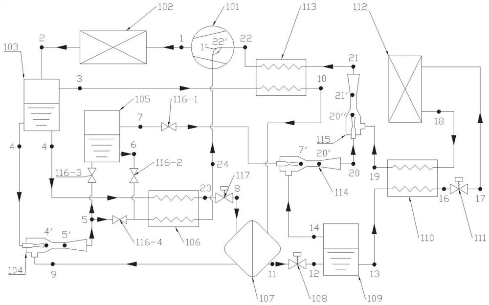
[0044] This embodiment provides a quasi-two-stage compression cycle system with ejector boost, which is a self-cascading quasi-two-stage compression refrigeration cycle system with ejector boost, such as figure 1 As shown, it includes a compressor 101, a condenser 102, an evaporator 112, an evaporative condenser 107, three gas-liquid separators, three ejectors and three regenerators.

[0045] In this embodiment, the existing equipment can be used for the regenerator, which has a superheated side and a supercooled side. The working fluid to be heated flows in from the inlet of the superheated side and flows out from the outlet of the superheated side, and the working fluid to be cooled is imported from the supercooled side. Inflow, outflow from the supercooled side outlet.

[0046] The superheated side of the regenerator means that the working fluid flows into the regenerator from the inlet of the superheated side, and flows out of the regenerator at the outlet of the superheat...

Embodiment 2

[0078] This embodiment provides a quasi-two-stage compression circulation system with ejector enhancement, which is a quasi-two-stage compression heat pump circulation system with ejector enhancement.

[0079] Such as Figure 5-Figure 6 As shown, it includes a compressor 101, the outlet of the compressor 101 is connected to the inlet of the condenser 102 through a pipeline, and the outlet of the condenser 102 is divided into two paths, one of which passes through the pipeline and the primary flow of the fourth ejector 118 The inlet is connected, and the other is connected to the inlet of the fourth pressure-reducing and cooling element through a pipeline. In this embodiment, the fourth pressure-reducing and cooling element adopts the fourth throttle valve 119 .

[0080] The outlet of the fourth ejector 118 is connected to the superheated side inlet of the fifth regenerator 120, the superheated side outlet of the fifth regenerator 120 is connected to the inlet of the fourth gas...


PUM


Abstract

The invention relates to an ejector enhanced quasi-two-stage compression type circulating system, which is an auto-cascade compression refrigeration circulation system and comprises a compressor, wherein the compressor is connected with a condenser; the condenser is connected with a first gas-liquid separator; one liquid outlet of the first gas-liquid separator is connected with a first ejector; the first ejector is connected with an air supply port of the compressor through a superheated side of a first heat regenerator; the other liquid outlet of the first gas-liquid separator is connected with an evaporation side inlet of an evaporative condenser through a supercooled side of the first heat regenerator and a depressurization and cooling element in sequence; an evaporation side outlet is connected with a secondary flow inlet of the first ejector; a gas outlet of the first gas-liquid separator is connected with the evaporator through a second heat regenerator, a condensation side of the evaporative condenser, a second gas-liquid separator and a third heat regenerator; and the evaporator is connected with an air suction port of the compressor through the third heat regenerator, a second ejector and a second heat regenerator. The system of the invention is high in variable working condition adapting capacity and small in throttling loss.

Description

technical field [0001] The invention relates to the technical field of vapor compression refrigeration and heat pump, in particular to a quasi-two-stage compression cycle system with ejector efficiency boost. Background technique [0002] The statements herein merely provide background information related to the present invention and do not necessarily constitute prior art. [0003] Current compression cycle systems include compression refrigeration cycle systems and compression heat pump cycle systems. [0004] For the compression refrigeration cycle system, with the development of industry and technological progress, many fields such as biomedicine, food industry, and cold chain logistics have put forward new requirements for low-temperature refrigeration technology, especially for the temperature range below -40 °C. strong. At present, the ways to realize the above-mentioned low-temperature area refrigeration mainly include: multi-stage compression refrigeration of sing...

Claims


Application Information

Patent Timeline
Patent Type & Authority Applications(China)
IPC IPC(8): F25B1/10F25B9/06F25B9/08F25B41/40F25B41/20F25B43/00F25B40/06
CPCF25B1/10F25B9/06F25B9/08F25B41/40F25B41/20F25B43/00F25B40/06
Inventor 陈壮赵红霞孔繁辰哈森陈海平
Owner SHANDONG UNIV
Learn More