Anchor rod-slurry-surrounding rock bonding strength testing method
What is AI technical title?
AI technical title is built by Patsnap AI team. It summarizes the technical point description of the patent document.
A technology of bonding strength and testing method, which is applied in the direction of installing anchor rods, strength characteristics, and using stable shear force to test the strength of materials, etc., to achieve the effect of accurate mechanical parameters and overcome uneven distribution of shear stress
Active Publication Date: 2016-09-28
SHANDONG UNIV OF SCI & TECH
View PDF4 Cites 4 Cited by
Summary
Abstract
Description
Claims
Application Information
AI Technical Summary
This helps you quickly interpret patents by identifying the three key elements:
Problems solved by technology
Method used
Benefits of technology
Problems solved by technology
The uniform distribution of shear stress on the bonded surface is achieved by unfolding the anchor structure, which overcomes the technical problems of uneven shear stress transmission in the traditional anchor pull-out test, and can accurately obtain the mechanical parameters of the anchor under different conditions, providing reasonable support for underground engineering. Provide scientific basis for protection design
Method used
Image
Click on the blue label to locate the original text in one second.
Reading with bidirectional positioning of images and text.
Examples
Embodiment 1
[0040] A method for testing the bond strength of a bolt-slurry-surrounding rock, comprising the following steps:
[0041] ①Take the bolt used in the project site, scan the surface of the bolt with a laser scanner, and obtain the topography data of the bolt surface;
[0042] ②Transmit the surface topography data of the anchor rod to the 3D printer, and print out the mold 5 with the surface topography of the anchor rod for making the anchor rod shear test piece 3 through the 3D printer, such as Figure 5shown;
[0043] ③Using the mold 5 as a template to make the anchor shear specimen 3, the anchor shear specimen 3 is in the shape of a cuboid as a whole, its upper surface has the same shape as the anchor surface, and the side and lower surfaces are smooth surfaces. The material is consistent with the material type of the anchor bolt on the project site;
[0044] ④Using the anchor shear test piece 3 as a template, pour the anchor bonding material on the anchor shear test piece 3...
Embodiment 2
[0048] ①Cut a section of the anchor rod at the project site as the anchor rod test piece, roll the anchor rod test piece through the plastic material under the set pressure condition, and leave the surface morphology of the anchor rod on the surface of the plastic material;
[0049] ② Use the plastic material surface as a template to make the anchor shear test piece 3. The anchor shear test piece 3 is in the shape of a cuboid as a whole, its upper surface has the same shape as the anchor surface, and the side and lower surfaces are smooth. Surface, the material used is consistent with the material type of the anchor bolt on the project site;
[0050] ③Using the anchor shear test piece 3 as a template, pour the anchor bonding material on the anchor shear test piece 3 to form a slurry layer 6, the thickness of the slurry layer 6 is the same as the thickness of the slurry in the project site Consistent, after the slurry layer 6 is solidified, the rock-like material is poured to f...
PUM
Abstract
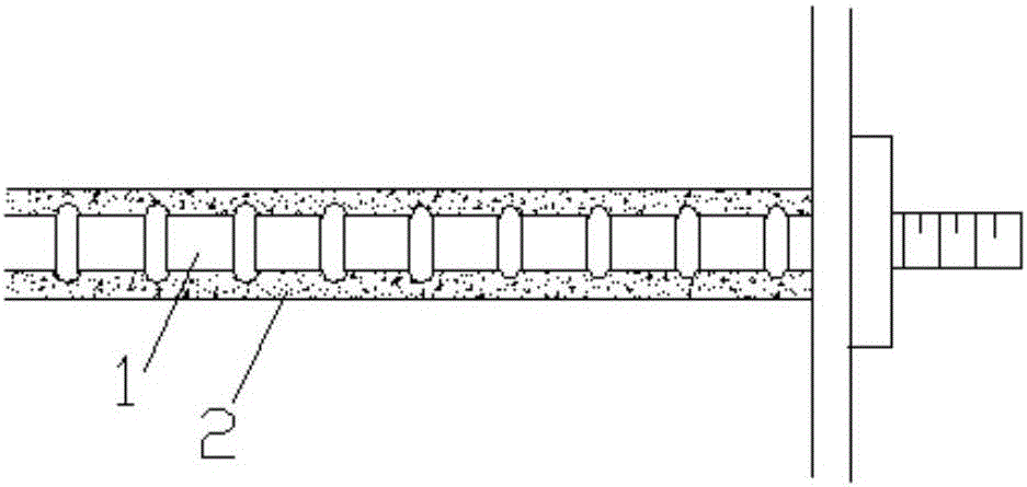
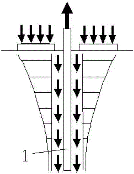
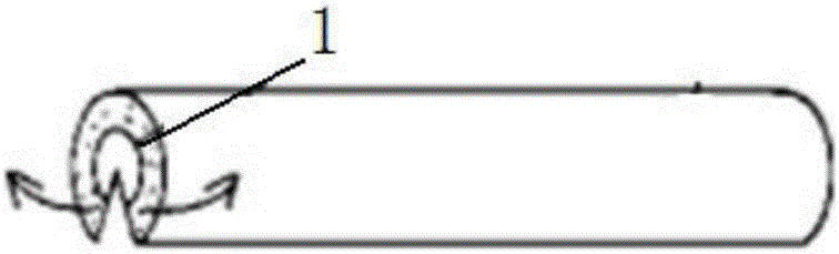
The invention relates to an anchor rod-slurry-surrounding rock bonding strength testing method. The method includes the following steps that 1, an anchor rod simulation body provided with a first surface is made, the concave-convex characteristic of the first surface is consistent with the appearance of the side wall surface of the anchor rod body, and the first surface is a plane; 2, a slurry layer for simulating a grouting material is poured on the first surface of the anchor rod simulation body; 3, a surrounding rock layer for simulating a surrounding rock material is poured on the solidified slurry layer, and the anchor rod simulation body, the slurry layer and the surrounding rock layer jointly form a simulation anchoring body; 4, a shearing test is conducted in the simulation stressed direction of the simulation anchoring body, and thus mechanical parameters reflecting the bonding strength of the anchoring body are obtained. Uniform distribution of shearing stress of a bonding face is achieved by unfolding an anchoring structure, the technical problem of uneven shear stress transfer in a traditional anchor rod drawing test is solved, the mechanical parameters of the anchoring body under different conditions can be obtained accurately, and a scientific basis is provided for reasonable supporting design of underground engineering.
Description
technical field [0001] The invention relates to the technical field of underground engineering, in particular to a method for testing the bonding strength of a bolt-slurry-surrounding rock. Background technique [0002] Anchor is one of the main support forms for underground engineering and rock slopes, and it is a tension member that goes deep into the formation. The technology is to drill holes in the rock or soil layer, bury the anchor rods in the drill holes, and then pour grout into the drill holes to fix the anchor rods on the rock (soil) layer of the slope or tunnel. In order to restrain the deformation and failure of the rock (soil) layer, play a supporting role. Relying on the bonding force between the grouting body and the ground in the anchorage section of the anchor rod, the gripping force of the anchor rod body and the grouting body, and the strength of the anchor rod body work together to bear the load acting on the supporting structure to maintain Stability ...
Claims
Application Information
Patent Timeline
Application Date:The date an application was filed.
Publication Date:The date a patent or application was officially published.
First Publication Date:The earliest publication date of a patent with the same application number.
Issue Date:Publication date of the patent grant document.
PCT Entry Date:The Entry date of PCT National Phase.
Estimated Expiry Date:The statutory expiry date of a patent right according to the Patent Law, and it is the longest term of protection that the patent right can achieve without the termination of the patent right due to other reasons(Term extension factor has been taken into account ).
Invalid Date:Actual expiry date is based on effective date or publication date of legal transaction data of invalid patent.

