A method of delayed coking

A technology of delayed coking and coking raw materials, applied in the field of delayed coking, which can solve the problems affecting the operation cycle and operation stability and safety of coking equipment and downstream processes, affecting the separation effect of vacuum fractionation tower, and the liquid fraction is easy to contain coke powder, etc. Achieve the effects of improving the quality of coking products, increasing the yield of liquid products, and extending the operating cycle

Active Publication Date: 2017-12-22
CHINA PETROLEUM & CHEM CORP +1
View PDF3 Cites 5 Cited by
  • Summary
  • Abstract
  • Description
  • Claims
  • Application Information

AI Technical Summary

Problems solved by technology

In CN101619237A, the decoking powder tank uses inert solid fillers to remove coke powder. When the coke powder content is slightly larger, on the one hand, the coke powder and viscous oil on the surface of the filler will greatly reduce the filling efficiency, and on the other hand, the bottom of the decoking powder tank The heavy component still contains a certain amount of coke powder, and this part of the heavy component is sent to the vacuum fractionation tower for further fractionation, which affects the separation effect of the vacuum fractionation tower, and the separated liquid fraction is also likely to contain coke powder
However, while the liquid recovery is increasing, the quality of coking rich gas, side stream products and circulating oil caused by coke fines and unreacted heavy components also declines obviously, which will also affect the operation cycle and operation stability of the coking unit and downstream processes , safety, similar to the conventional process, which limits the further improvement of the liquid recovery by increasing the outlet temperature of the heating furnace
In particular, the improved process can only be limited to low cycle ratio operation. When the raw material fluctuations or abnormal working conditions need to increase the cycle ratio to ensure safe production, the operation cannot be adjusted, resulting in relatively large limitations of the process method.

Method used


Image

  • A method of delayed coking
  • A method of delayed coking
  • A method of delayed coking

Examples


Embodiment 1

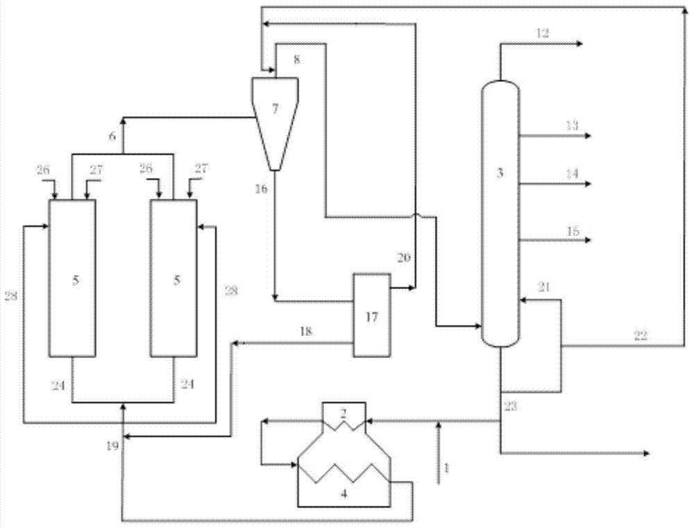
[0078] This embodiment adopts figure 1 The process flow, this embodiment illustrates the situation of using a higher circulation ratio of 0.4 and a higher furnace outlet temperature of 503°C.

[0079] Fresh coking raw material (vacuum residue) from pipeline 1 is mixed with part of fractionation tower bottom oil from pipeline 23, and then enters the convection section 2 and radiation section 4 of the heating furnace in sequence, and enters the top of the tower as a spherical head after heating up to 503°C coke tower 5 and carry out the coking reaction at 0.15MPa, and the circulation ratio is 0.4:1 (that is, the feed mass ratio of the fractionation tower bottom oil to the fresh coking raw material); 24h), the generated coked oil gas enters the cyclone separator 7 in a tangential manner, and the residence time of the coked oil gas in the cyclone separator is 1 minute. The mixture is injected into the top of the cyclone separator as washing oil (the mass ratio of the upper layer ...

Embodiment 2

[0081] This embodiment adopts figure 1 The flow process is carried out according to the method of Example 1, the difference is that after the fresh coking raw material (vacuum residue) from the pipeline 1 is mixed with the part fractionation bottom oil from the pipeline 23, it enters the heating furnace convection section 2, radiation Section 4, after heating up to 504°C, it enters the coke tower 5 with a spherical head at the top of the tower, and the circulation ratio is 0.1:1, the length of the coke tower feed position from the lower end of the cylinder accounts for 6 / 10 of the entire cylinder length; sedimentation The mass ratio of the lower layer oil in the tank to the feed of fresh coking raw materials is 0.02:1; the mass ratio of the washing oil injection to the feed of fresh coking raw materials is 0.04:1. The mass ratio of the bottom oil of the 22 partial fractionation tower is 1:1; the weight ratio of cooling oil and desalted water is 0.2:1, and the weight ratio of t...

Embodiment 3

[0083] In this embodiment, the attached figure 1 The flow process of the method is carried out according to the method of embodiment 1, and the difference is that after the fresh coking raw material (vacuum residue) from pipeline 1 is mixed with the part fractionation tower bottom oil from pipeline 23, it enters the heating furnace convection section 2 and radiation section successively 4. After heating up to 505°C, it enters the coke tower 5 with a spherical head at the top of the tower, and the circulation ratio is 0.1:1; the length of the coke tower feed position from the lower end of the cylinder accounts for 7 / 10 of the entire cylinder length; the washing oil The mass ratio of injection amount to fresh coking raw material feed is 0.05:1, and the mass ratio of the upper layer oil of the settling tank from pipeline 20 in the washing oil to the partial fractionation tower bottom oil from pipeline 22 is 4:1; the cooling oil and demineralized water The weight ratio is 0.3:1, a...


PUM

PropertyMeasurementUnit
diameteraaaaaaaaaa
diameteraaaaaaaaaa

Abstract

The invention discloses a delayed coking method, which comprises the steps of heating the mixture containing fresh coking raw materials and circulating oil at the bottom of a fractionation tower through the radiant section of a heating furnace, and then mixing it with the heavy settled oil after the bottom oil has been settled and separated in a cyclone separator As a delayed coking raw material, it is injected into the coke tower from the upper part and the bottom of the coke tower for delayed coking reaction to generate coke and coked oil gas; the obtained coked oil gas is sent to the cyclone for separation, and the washing oil is injected into the top of the cyclone separator, Obtain the bottom oil of the cyclone separator and the purified coker gas; send the purified coker gas to the fractionation tower for fractionation to obtain gas, gasoline, diesel oil, coker gas oil and fractionation tower bottom oil; this method can improve the yield of liquid products rate and improve coking product quality, and can be applied to a wide range of cycle ratios.

Description

technical field [0001] The invention relates to a delayed coking method. Background technique [0002] As the world's crude oil resources become heavier and worse, the consumption of heavy fuel oil decreases and the demand for light oil products increases, heavy oil deep processing technology has become the focus of the development of the world's oil refining industry. At present, the main technologies to increase the conversion depth of heavy oil and increase the output of light oil products are still coking, catalytic cracking of residual oil and hydrotreating of residual oil. As a thermal processing process of deep thermal cracking, delayed coking can convert heavy oil into dry gas, liquefied gas, coker gasoline, coker diesel, coker wax oil and coke. It has the advantages of strong raw material adaptability and obvious economic benefits. One of the most important heavy oil conversion technologies. Usually, the sum of the yields of coked gasoline, coked diesel oil and co...

Claims


Application Information

Patent Timeline
Patent Type & Authority Patents(China)
IPC IPC(8): C10G55/00
Inventor 阎龙申海平刘自宾范启明
Owner CHINA PETROLEUM & CHEM CORP
Why Eureka
Try Eureka