Spray head

a spray head and head technology, applied in the field of spray heads, can solve the problems of not meeting the requirements in a satisfactory way, and achieve the effects of low cost, convenient assembly and disassembly, and convenient cleaning

Inactive Publication Date: 2006-05-09
ASEPT INT
View PDF5 Cites 69 Cited by
  • Summary
  • Abstract
  • Description
  • Claims
  • Application Information

AI Technical Summary

Benefits of technology

The present invention aims to solve the problem of difficulty in assembling and cleaning spray heads by providing them with easy-to-assemble, disassemble, and clean features. This results in a spray head that is cost-effective to manufacture.

Problems solved by technology

The technical problem addressed by this patent is how to create spraying nozzles for foods like ketchup, mayonnaise, and salad dressings that can easily detach from their components for cleaning without being too complicated to re-assemble once done. Current designs have multiple parts that make it hard to keep them all clean and efficient.

Method used


Image

  • Spray head
  • Spray head
  • Spray head

Examples


Embodiment Construction

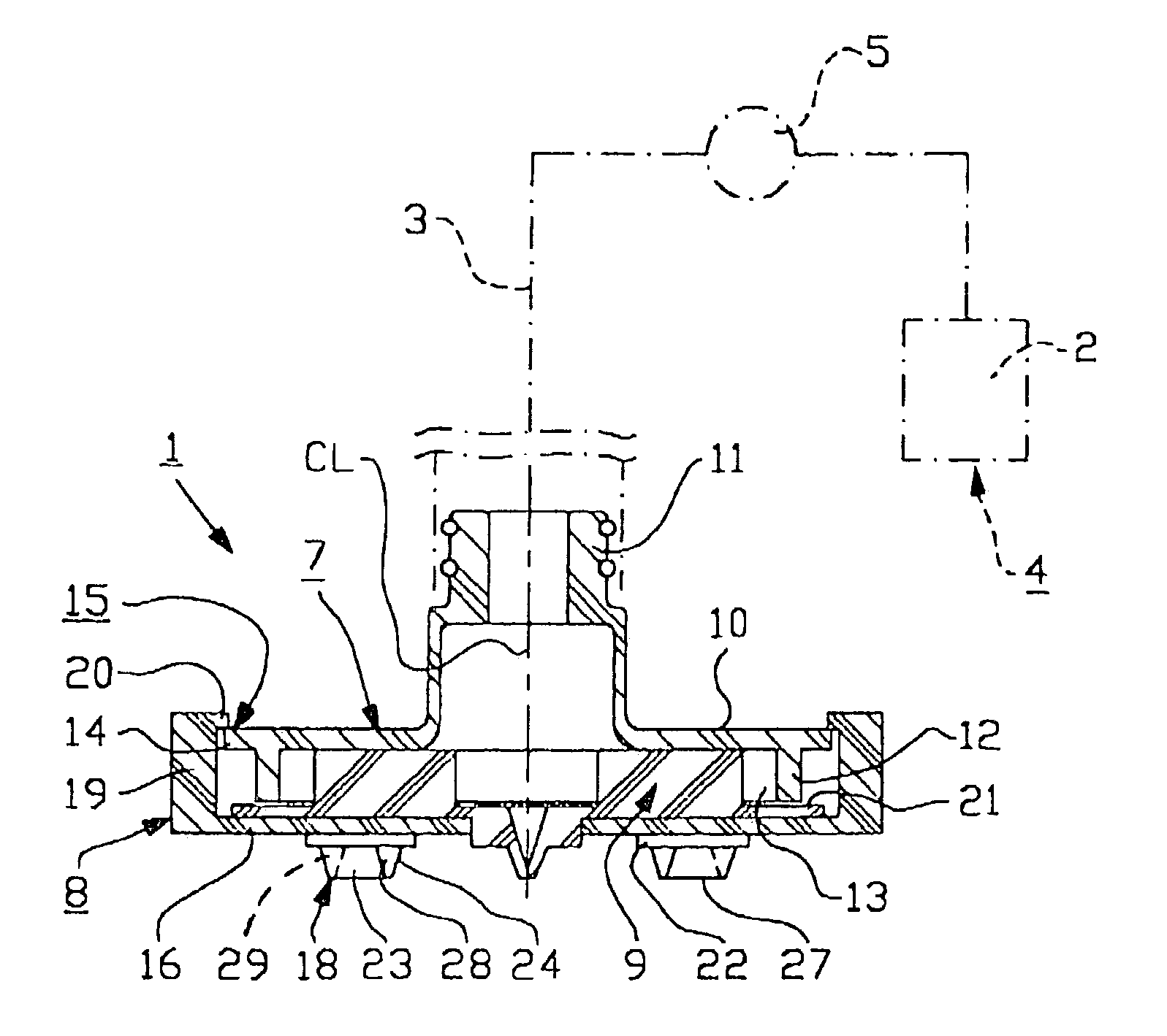
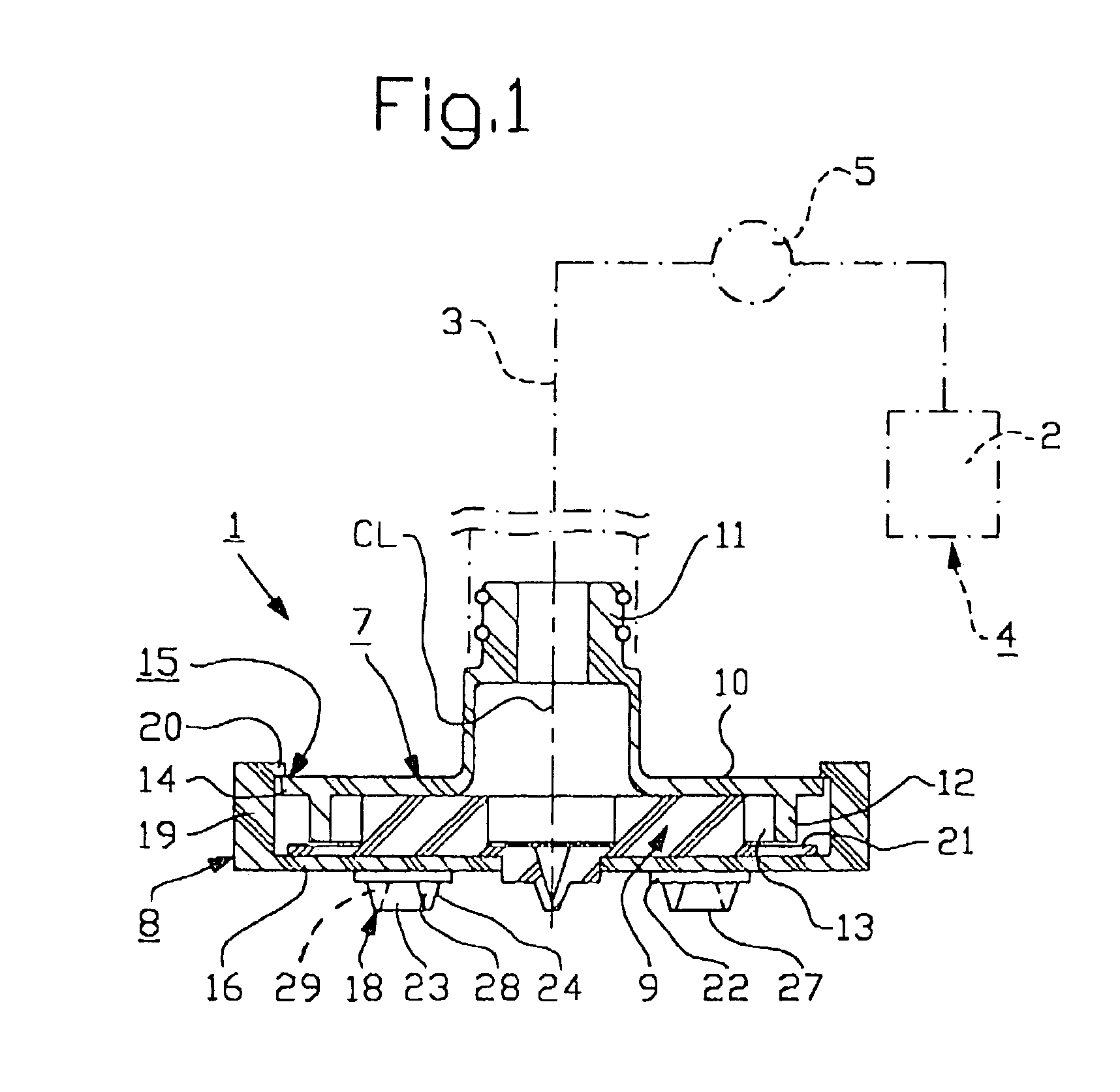
[0013]FIG. 1 illustrates a spray head 1 which is adapted for discharging or spreading liquid or semi-liquid products 2, e.g. foodstuff such as ketchup, mustard, dressing, sauces etc. with or without solid constituents, onto a suitable place or object, e.g. a dish of some kind. The spray head 1 is through a feed conduit 3 connected or connectable to a product container 4, e.g. a plastic bag or similar. The feed conduit 3 may be a hose and / or a pipe. A product feeder 5, e.g. a pump or similar, is provided to feed the product from the product container 4, through the feed conduit 3 and the spray head 1, which is adapted to discharge several product streams 6 (see FIG. 6) towards the intended place or object such that the product is distributed or spread thereon.

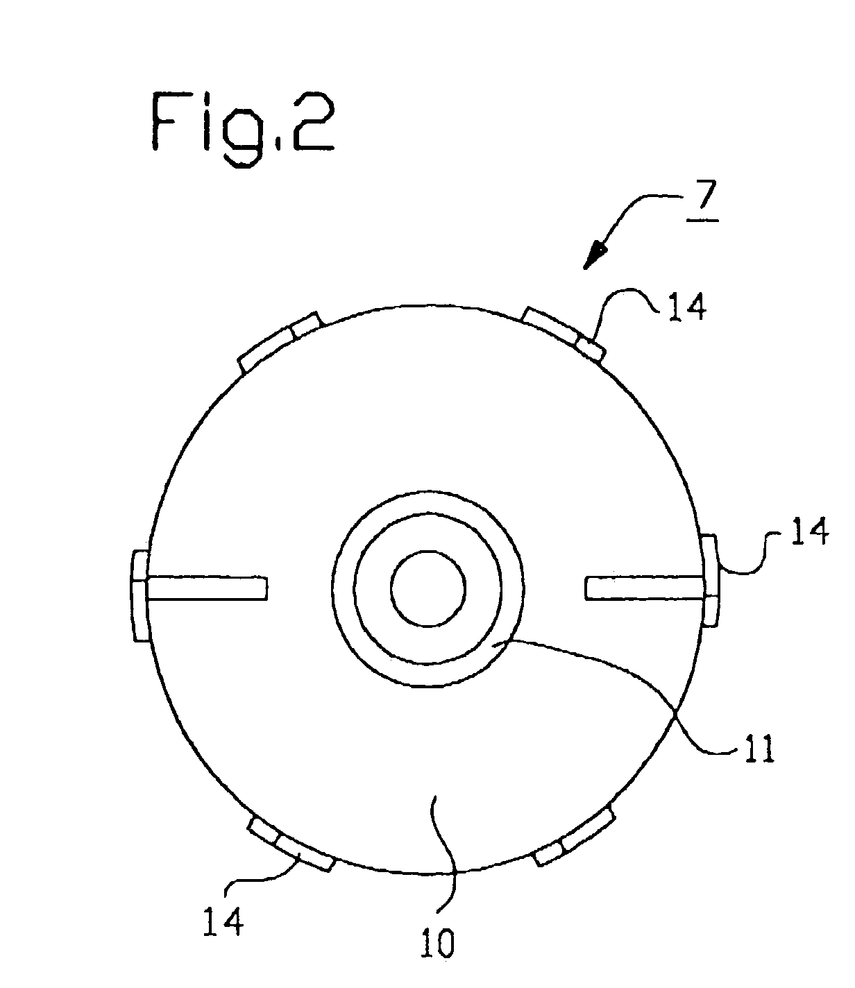
[0014]The spray head 1 consists preferably of three separate members, namely an upper coupling member 7, a lower coupling member 8 and a nozzle member 9 provided therebetween.

[0015]The upper coupling member 7 includes preferably...


PUM


Abstract

The present invention relates to a spray head for spreading liquid or semi-liquid products, preferably foodstuff. A product feeder (5) is provided to feed or convey a product (2) through a feed conduit (3) from a product container (4) to the spray head (1) and spraying nozzles (18) are provided to spread the product (2) when it is discharged from the spray head (1). The spray head (1) comprises three separate members, namely an upper coupling member (7), a lower coupling member (8) and a nozzle member (9) provided therebetween. The upper coupling member (7) is connected to the lower coupling member (8) and to the feed conduit (3). The nozzle member (9) and/or the upper coupling member (7) define, when the upper and lower coupling members (7, 8) are interconnected, distributing spaces (13) for distributing product (2). The spraying nozzles (18) of the nozzle member (9) are provided to open and to close. The nozzle member (9) is removable from the upper and lower coupling members (7, 8) when these members have been disconnected from each other.

Description


Claims


Application Information

Patent Timeline
Owner ASEPT INT
Why Eureka
Try Eureka